
Composite railroad tie and method of manufacture

a technology of composite railroad ties and manufacturing methods, applied in the direction of rail fasteners, coatings, ways, etc., can solve the problems of affecting the service life of the railroad, and affecting the use of the railway, so as to reduce weight and cost, increase stiffness and quality, and increase strength

Inactive Publication Date: 2007-08-16
FORCEPRO L L C
View PDF18 Cites 20 Cited by
  • Summary
  • Abstract
  • Description
  • Claims
  • Application Information

AI Technical Summary

Benefits of technology

[0018] Another objective of the present invention is to provide a railroad tie which has one or more cavities formed into at least one of the faces to provide a lighter railroad tie and one that can be better gripped by the material of the roadbed for improved lateral stability.
[0025] It is a further object of the present invention to provide an improved process and system for injection molding composite ties. The system being highly automated to help lower labor and production costs while producing high quality ties of the present design.

Problems solved by technology

A major safety problem is derailment.
Derailments can cost millions of dollars in damage and loss of use of a railway.
The leading cause of this problem is a lack of lateral stability.
This happens when the gravel on either end of the tie, as well as the friction between the gravel and the sides and bottom of the tie, cannot restrain the forces exerted on the tie by the train rolling over the rails above it.
The increased demand for wood in today's economy, coupled with the limited supply, has driven up the cost of wooden railroad ties.
When the railroad ties are in use they are subjected to conditions which greatly reduce the useful life of the railroad tie.
These include exposure to moisture, wood destroying insects, and freezing and thawing.
These, coupled with the forces and vibrations exerted on the ties by the trains, lead to a limited useful life for the railroad ties.
While concrete provides a solid material for a tie, it can tends to be excessively heavy and hard to move.
Using sand as the filler in this thermoplastic mix has the same draw back as concrete in that it is excessively heavy.
The sand also increases the wear on the die used to extrude the tie.
This means that the railroad tie is heavier than necessary.
It is also more expensive than necessary because it contains more material than is needed for its application.
This means that the production must either have a larger cooling bath or a slower production rate, either which adds to the cost of the ties.
Other features of prior art for molding large structural members similar to ties require cumbersome cooling processes.
This designs adds to the material cost of the structure as well as the labor and manufacturing cost due to the additional necessary steps.
While this presents certain advantages over using a cooling core, the process of submerging the entire mold presents its own set of problems such as having to maintain a cooling tank large enough to accommodate the molds, handling of the molds with the added weight of the piling inside and the cost of having multiple molds on hand to keep production going while the molds are cooling.
One of the problems that has plagued the injection molding industry is the inability to use a split mold on these extra large structures.
This leads to problems in removing the completed part from the mold, which in turn leads to low production rates and higher production costs.
Thus further limiting the efficiency of this arrangement.
All in all this proves to be a very inefficient process.

Method used


Image

  • Composite railroad tie and method of manufacture
  • Composite railroad tie and method of manufacture
  • Composite railroad tie and method of manufacture

Examples


Embodiment Construction

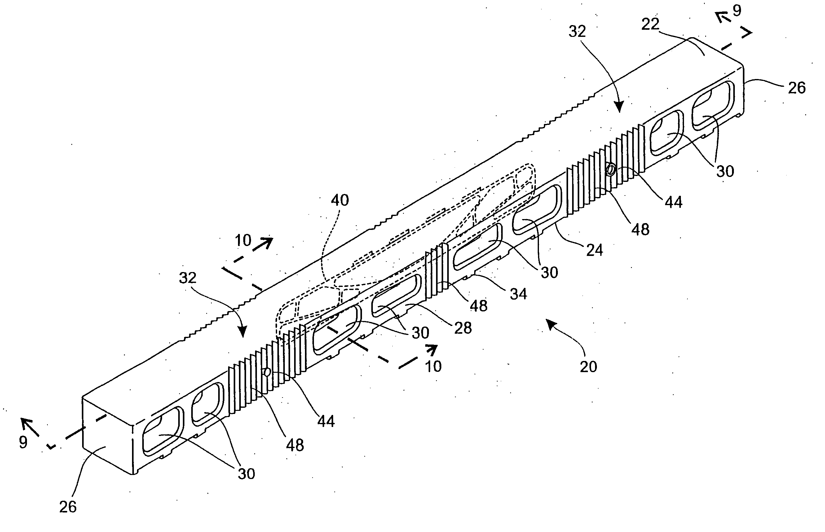
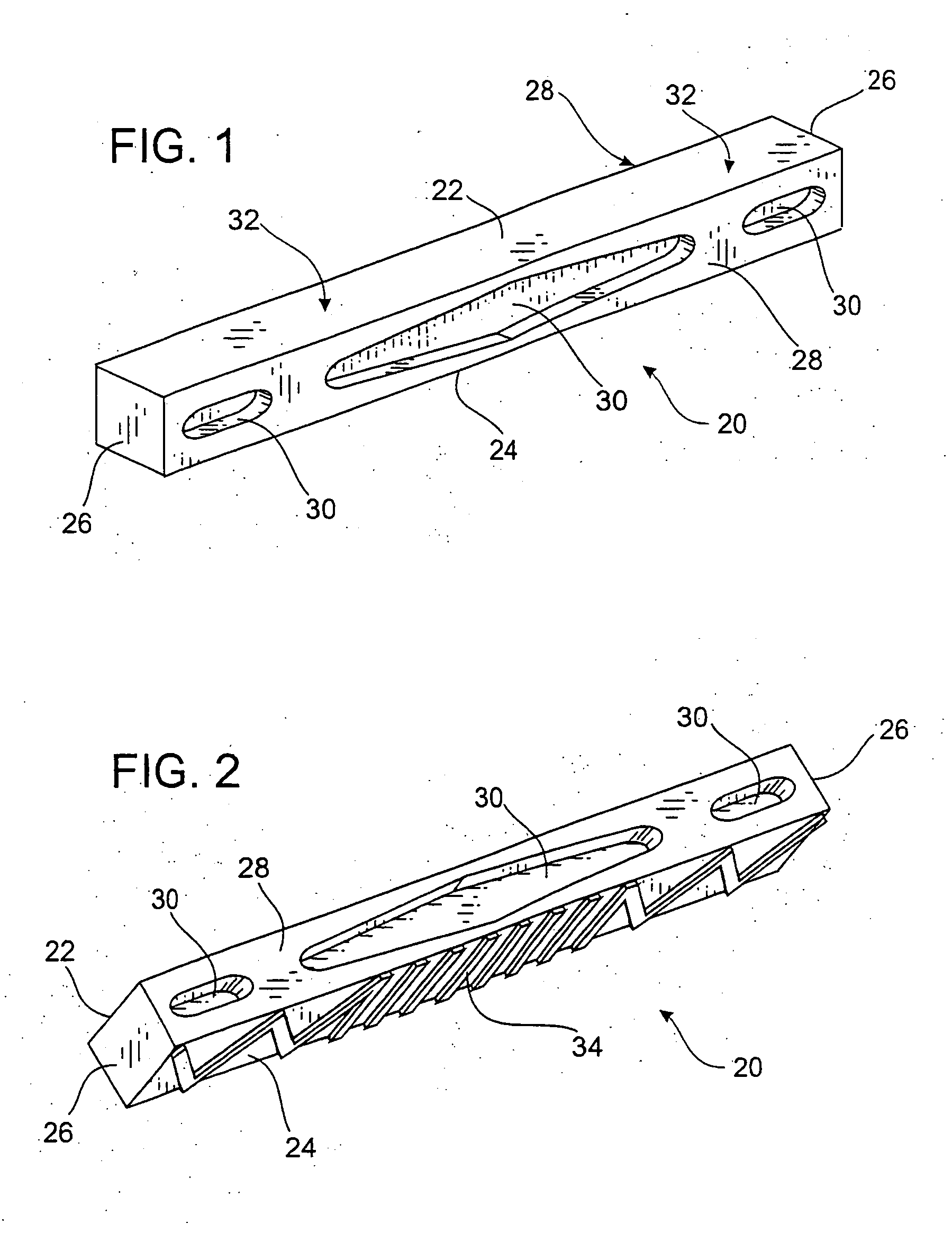
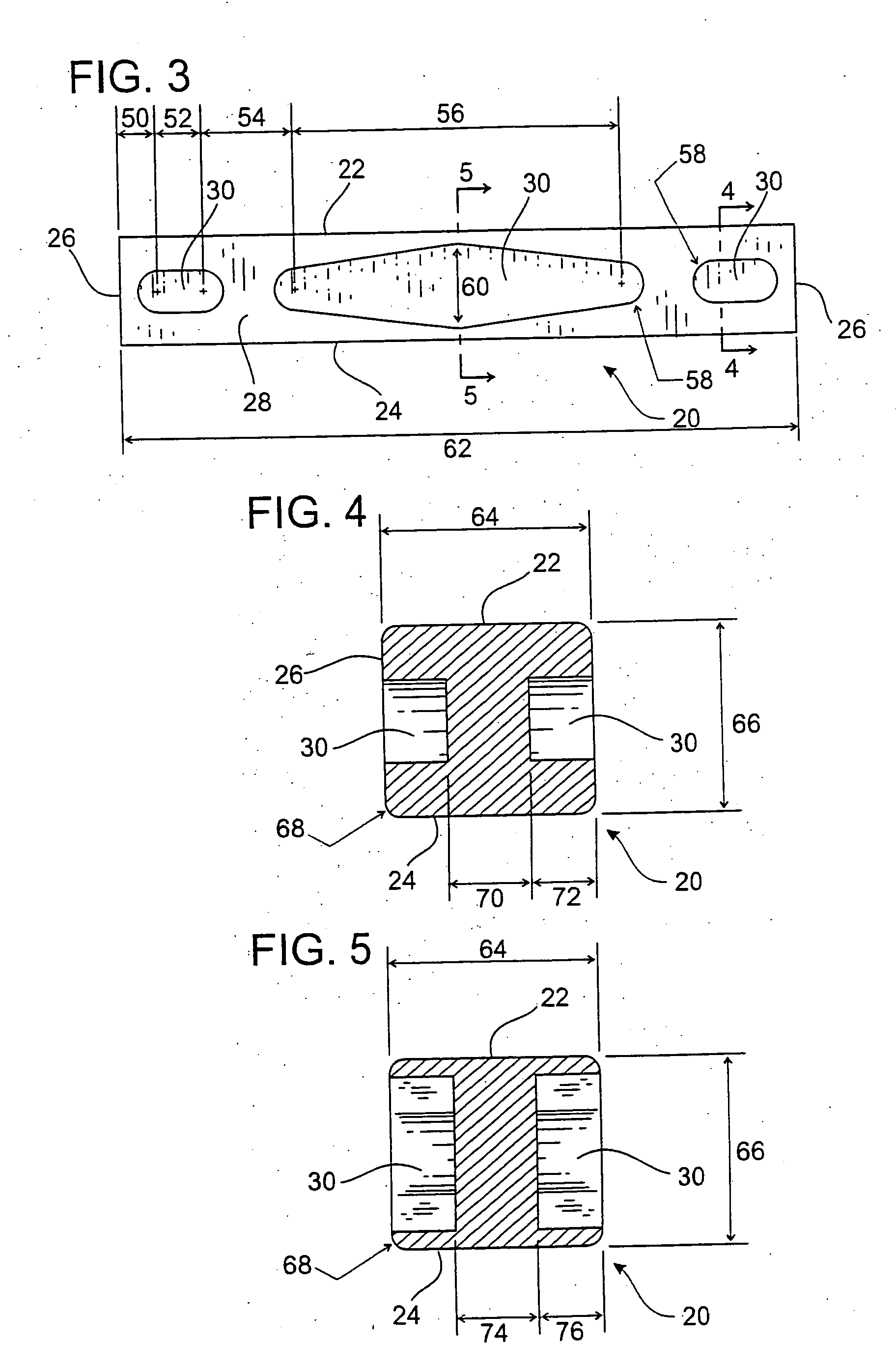
[0054]FIG. 1 is a prospective view of the preferred embodiment of the improved composite tie 20. The improved composite tie 20 has a top 22, a bottom 24, two opposing ends 26, and two opposing sides 28. The improved composite tie shown in FIG. 1 has three cavities 30 located in the side 28 of the tie 20. The backside 28 (not shown) of the tie 20 also has three cavities 30 which correspond to those shown in the front side 28 shown in FIG. 1. When the tie 20 is installed, the rail is attached to the tie 20 generally in the area indicated 32. The rails are attached to the tie 20 using railroad spikes, screws, brackets and / or other fasteners typically well known in the industry.

[0055] When the tie 20 is in use, the weight and force from the train is transferred through the rails generally into the area indicated as 32, the majority of these forces are in compression. As such, the railroad tie 20 does not need to be a solid rectangular block in order to handle these loads. Therefore, th...


PUM

PropertyMeasurementUnit
Areaaaaaaaaaaa

Abstract

An improved mold and method of manufacture for an improved railroad tie or other structural member. The improved railroad tie or structural member being fabricated using an injection molding process with various thermoplastic resins and fillers. The improved mold used has a cooling cavity which helps cool the structural member while still in the mold. The improved insert allows an automated molding system to be used for greater production rates.

Description

CROSS-REFERENCE TO RELATED APPLICATIONS [0001] This application is a continuation-in-part and claims the benefit of the filing of pending U.S. patent application Ser. No. 11 / 114,620 which in turn is a continuation-in-part of U.S. patent application Ser. No. 10 / 837,978 which in turn is a continuation-in-part and claims the benefit of the filing of U.S. Provisional Patent Application Ser. No. 60 / 516,697, entitled “Improved Composite Railroad Tie and Method of Manufacture”, filed on Nov. 3, 2003, and the specifications of these prior applications are incorporated herein by reference.BACKGROUND OF THE INVENTION [0002] 1. Field of the Invention [0003] The present invention relates to an improved railroad tie and process of manufacture. More particularly, the improved railroad tie is fabricated out of various thermoplastic resins and fillers using an injection molding and cooling process. Part of the cooling is accomplished using a cooling cavity located in the mold. Further the present i...

Claims


Application Information

Patent Timeline
IPC IPC(8): E01B21/04
CPCE01B3/44E01B3/46B29C45/73B29C45/14819B29C45/7207B29C45/14631
Inventor KIRCHMER, BRYANKIRCHMER, ROBERTMCINTOSH, EUGENE
Owner FORCEPRO L L C
Learn More