Motor, lens barrel, camera system, and method for producing motor

Inactive Publication Date: 2007-08-16
NIKON CORP
View PDF11 Cites 16 Cited by
  • Summary
  • Abstract
  • Description
  • Claims
  • Application Information

AI Technical Summary

Benefits of technology

[0045]According to the present invention, it is possible to realize the motor which

Problems solved by technology

Any lubricating oil cannot be used for the frictional contact surfaces of the alumite layer and the Ni layer.
However, the conventional oscillatory wave motor has involved the following problems.
That is, when the frictional contact surface between the oscillator and the movable member is subjected to the frictional driving for a long period of time, the stability of the frictional contact surface cannot be maintained due to the appearance of the abrasion powder generated by any considerable damage of the frictional contact surface resulting from the small difference in hardness between the alumite layer and the Ni layer and/or the deterioration of the alumite layer.
Therefore, problems arise such that any abnormal sound or noise is generated and/or the driving efficiency is lowered.
Further, the following problems arise.
That is, the frictional contact surface becomes unstable due to the abrasion, and that when the driving operation is performed for a long period of time under the high load, then the number of revolutions is suddenly lowered, it is thus impossible to maintain the stable driving, and the driving performance is deteriorated.
Therefore, problems arise such th

Method used


Image

  • Motor, lens barrel, camera system, and method for producing motor
  • Motor, lens barrel, camera system, and method for producing motor
  • Motor, lens barrel, camera system, and method for producing motor

Examples


first embodiment

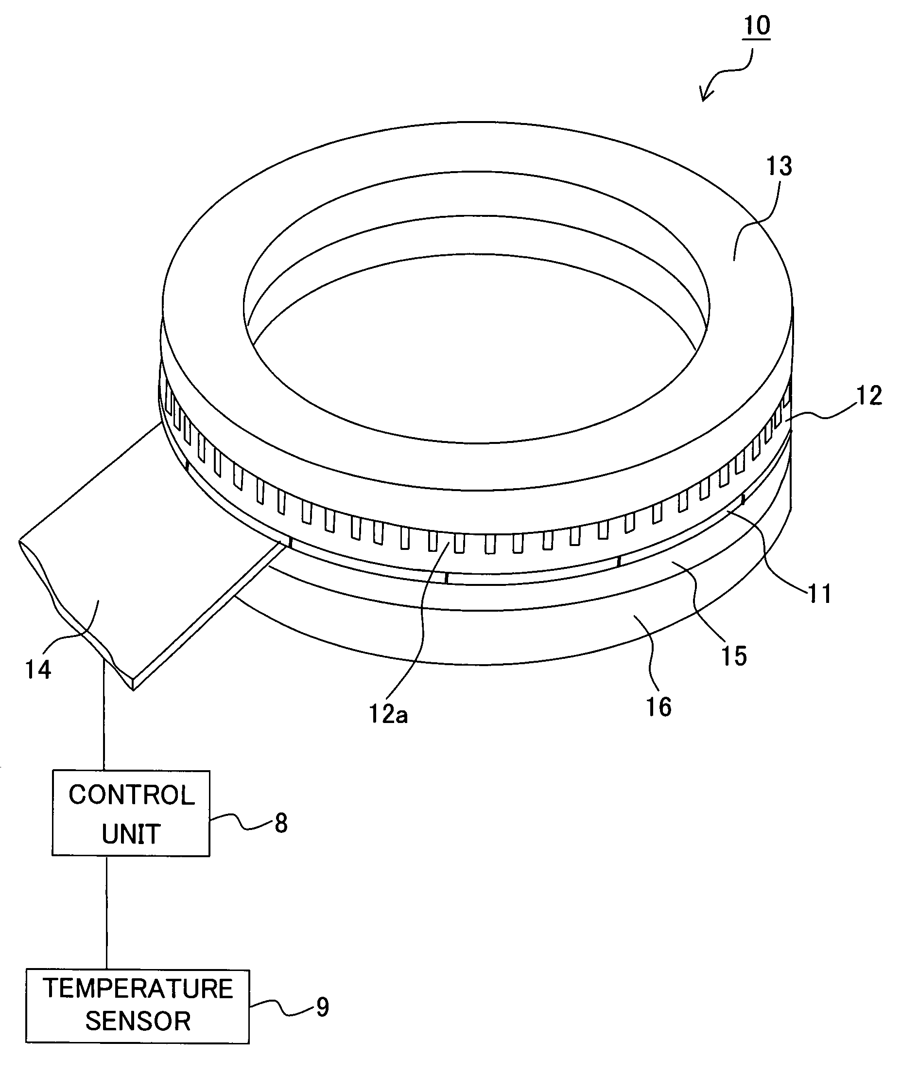
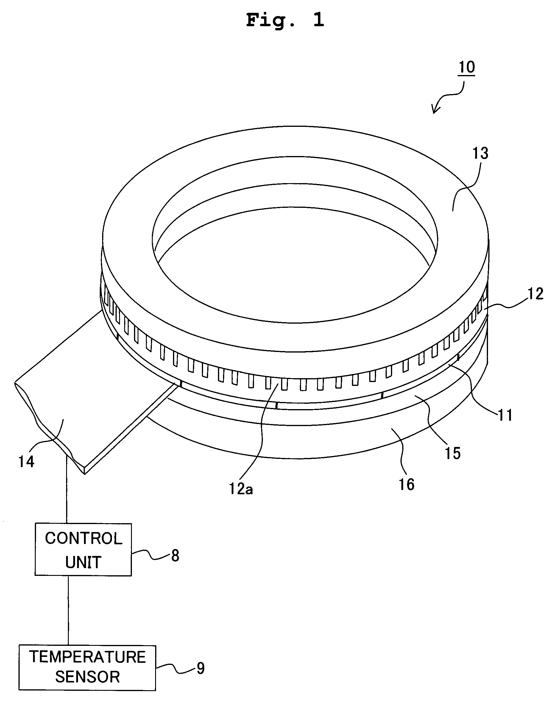
[0055]FIG. 4 shows a sectional view illustrating a camera provided an oscillatory wave motor according to a first embodiment.

[0056]A camera 1 of this embodiment includes a camera body 2 which has an image pickup device 6, and a lens barrel 3. The lens barrel 3 is an exchangeable lens which is detachable with respect to a mount portion of the camera body 2. The camera 1 of this embodiment is illustrative of a case in which the lens barrel 3 is the exchangeable lens. However, there is no limitation thereto. For example, it is also allowable to adopt a camera provided with a lens barrel which is constructed integrally with the camera body.

[0057]The lens barrel 3 includes, for example, a lens 4, a cam cylinder 5, and an oscillatory wave motor 10. In this embodiment, the oscillatory wave motor 10 is used as a driving source for driving the lens 4 when the camera 1 is subjected to the focusing operation. The driving force, which is obtained from the oscillatory wave motor 10, is transmitt...

second embodiment

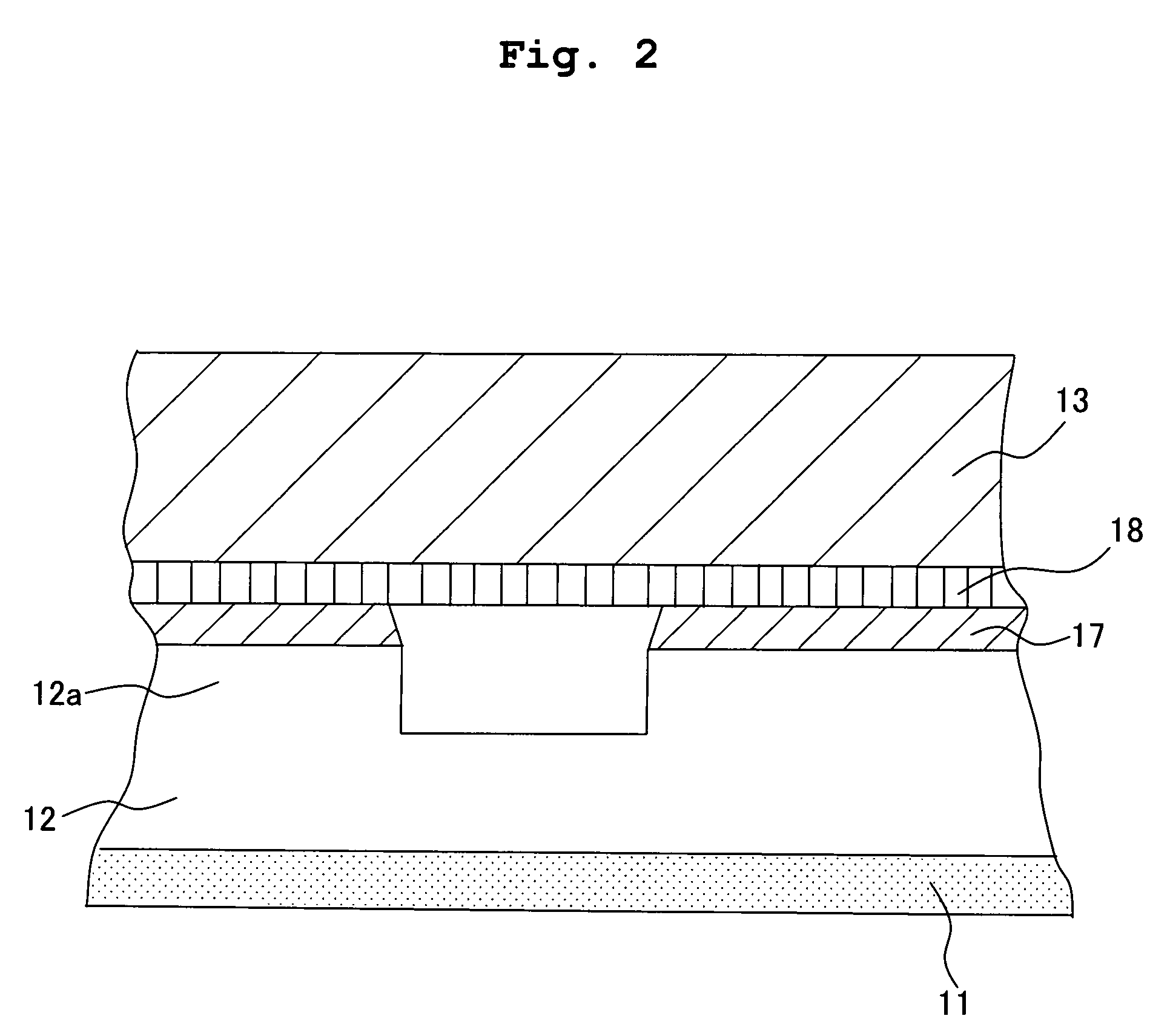
[0152]An oscillatory wave motor of a second embodiment is different from the oscillatory wave motor 10 described in the first embodiment in the film thickness, the additive, the material to serve as the main agent for the epoxy resin film 17, and the like. Therefore, the portions, which function in the same manner as those of the first embodiment described above, are designated by the same reference numerals, any duplicate explanation of which will be appropriately omitted.

[0153]An epoxy resin film 17 of this embodiment is formed of an epoxy resin which contains 20% by weight of PTFE, 10% by weight of silicon beads having a particle size of 6 μm, and 3.5% by weight of conductive carbon and which is blended with a phenol resin as a curable prepolymer. The maximum height roughness Rz (JIS B0601-2001) of a surface of the epoxy resin film 17 is 0.4 μm, and the film thickness is 30 μm.

[0154]The epoxy resin film 17 of the second embodiment is formed by performing approximately the same st...

third embodiment

[0248]FIG. 3 illustrates an oscillatory wave motor according to a third embodiment.

[0249]The oscillatory wave motor 20 according to the third embodiment includes an elastic member 22 and a piezoelectric member 21 for forming an oscillator, a movable member 23, a support member 26, an output shaft 28, and the like. The oscillatory wave motor 20 is provided for an unillustrated camera, and the oscillatory wave motor 20 is used as a driving source for driving a driven member which performs the zooming operation of an unillustrated lens barrel.

[0250]The oscillator is a member having a substantially annular shape including the elastic member 22, the piezoelectric member 21 joined to the elastic member 22, and the like. The progressive oscillatory wave is generated in accordance with the expansion and contraction of the piezoelectric member 21.

[0251]The elastic member 22 is a member having a substantially annular shape formed of a metal such as stainless steel having a large resonance sha...


PUM

PropertyMeasurementUnit
Percent by massaaaaaaaaaa

Abstract

An oscillatory wave motor, a lens barrel, and a camera system are provided, which have long service lives and which are stable. An oscillatory wave motor includes an oscillator which generates oscillation on an elastic member in accordance with excitation of an electromechanical conversion element, and a relative movement member which is pressurized to make contact with the oscillator and which moves relative to the oscillator in accordance with the oscillation. The oscillatory wave motor has an epoxy resin film formed of silicon beads and an epoxy resin and which is formed on at least one of frictional contact surfaces of the oscillator and the relative movement member.

Description

BACKGROUND OF THE INVENTION[0001]1. Field of the Invention[0002]The present invention relates to a motor, a lens barrel, a camera system, and a method for producing the motor.[0003]2. Description of the Related Art[0004]Conventionally, in the case of an oscillatory wave motor which is one type of the motor, an oscillator is subjected to the frictional contact with a relative movement member which serves as a relative movable member. The oscillatory wave, for example, the ultrasonic oscillation or vibration, which is generated on the oscillator, is transmitted to the relative movement member, and the relative movement member is frictionally driven. Therefore, it is necessary that the oscillator efficiently transmits the applied ultrasonic oscillation to the relative movement member. Therefore, a highly elastic material, for example, an iron-based or stainless steel-based metal material is used for the oscillator.[0005]A variety of attempts have been made for the frictional contact su...

Claims


Application Information

Patent Timeline
IPC IPC(8): H02N2/00H01L41/00
CPCC08G59/4028C08G59/621C08L27/18C08L33/00C08L63/00C08L75/04G02B7/08H02N2/163H02N2/007C08L2666/02H02N2/00
Inventor KOBAYASHI, MINAINOUE, MAMORU
Owner NIKON CORP
Why Eureka
Try Eureka