Image stabilizer, lens device and imaging apparatus

a technology which is applied in the field of image stabilization and lens device, which can solve the problems of increasing power consumption, preventing and increasing the temperature inside the apparatus, so as to prevent the position of the correcting lens from being stabilized

Inactive Publication Date: 2007-08-16
SONY CORP
View PDF6 Cites 49 Cited by
  • Summary
  • Abstract
  • Description
  • Claims
  • Application Information

AI Technical Summary

Benefits of technology

[0010] Japanese Patent Application Publication No. 2000-258813 discloses a second example of an image stabilizer in related art, for example. In this Patent Reference, there is described one relating to an image stabilizer used for optical equipment and a lens barrel using the image stabilizer. The image stabilizer described in this Patent Reference (hereinafter referred to as “a second related-art example”) is an image stabilizer which stabilizes images by moving part of a imaging lens to the inside of a surface perpendicular to an optical axis, including: a lens holding frame, a first guide, a second guide, a first driver, a second driver, and a position detector. The lens holding frame holds a correcting lens. The first guide guides the lens holding frame to move in a first direction within a surface perpendicular to the optical axis. The second guide guides the lens holding frame to move in a second direction perpendicular to the first direction. The first driver and second driver drive the lens holding frame in the first and second directions, respectively. The position detector detects the position of the correcting lens. In this image stabilizer, the first guide and the second driver, or the second guide and the first driver are arranged to partially overlap, when seen from an optical axis direction.
[0012] However, regarding the aforementioned first and second related-art examples, a holding frame having a correcting lens is guided and supported in a movable manner in a first direction and second direction perpendicular to each other; and the guiding and supporting mechanism includes a combination of a shaft and a bearing portion, two pairs of which make one set. In this case, there may need some gap between the shaft and bearing portion of each combination in order for the holding frame to move, which causes a problem of looseness when moving, and the looseness not only makes smooth motion difficult but also makes the position of the correcting lens unstable.
[0013] Further, in the case of an image stabilizer apparatus being used with an optical axis of a correcting lens directed in a horizontal direction, in other words, in an imaging apparatus whose lens device, in which an optical axis of a lens system is directed in a horizontal direction, has the aforementioned image stabilizer apparatus, a holding frame holding the correcting lens is used with its moving direction set in the gravitational direction. Therefore, a moving frame may be required to be held at a predetermined height by supplying power to a coil all the time. As a result, there is an increase in the consumption of power, hence, causing the power consumption to increase in a battery and the temperature inside an apparatus to rise by the heat of an actuator and the like.
[0014] The present inventor has recognized the followings. Regarding an image stabilizer in related art, a holding frame holding a correcting lens is guided and supported by a supporting mechanism formed of a combination of a shaft and a bearing portion, two pairs of which make one set. Therefore, backlash between the shaft and bearing portion may prevent the holding frame from moving smoothly, and may prevent the position of the correcting lens from being stabilized. Further, if the moving direction of a moving frame corresponds with the gravitational direction, it is necessary to prevent the moving frame from going down by gravity and to hold the moving frame in a predetermined position by supplying power to a coil all the time. Accordingly, there is an increase in the consumption of power, hence, causing the power consumption to increase in a battery and the temperature inside an apparatus to rise by the heat of an actuator and the like.
[0015] According to an embodiment of the present invention, there is provided an image stabilizer including a driver having a coil and a magnet capable of moving relatively. The driver controls a correcting lens held on a moving frame to move in a first direction perpendicular to an optical axis of a lens system and in a second direction perpendicular to the first direction and the optical axis, and controls an optical axis of the correcting lens to correspond with the optical axis of the lens system, stabilizing images. One of the coil and the magnet is fixed to the moving frame and the other is fixed to a supporting frame supporting the moving frame in a movable manner. Further, the driver includes a first coil for moving the correcting lens in the first direction, a second coil for moving the correcting lens in the second direction, and a magnet for applying magnetic force to the first coil and the second coil. The first coil and the second coil are disposed such that thrust generated from a thrust-generating portion of the first coil and thrust generated from a thrust-generating portion of the second coil are directed in the first direction and the second direction by the magnetic force of the magnet. Further, a magnetic member attracted to or repelled by the magnet is provided in the vicinity of the first coil and the second coil on the moving frame or the supporting frame to which both the coils are fixed.
[0016] According to an embodiment of the present invention, there is provided a lens device including an image stabilizer which has a driver including a coil and a magnet capable of moving relatively. The driver controls a correcting lens held on a moving frame to move in a first direction perpendicular to an optical axis of a lens system and in a second direction perpendicular to the first direction and the optical axis, and controls an optical axis of the correcting lens to correspond with the optical axis of the lens system, stabilizing images. One of the coil and the magnet is fixed to the moving frame and the other is fixed to a supporting frame supporting the moving frame in a movable manner in the image stabilizer. Further, the driver includes a first coil for moving the correcting lens in the first direction, a second coil for moving the correcting lens in the second direction, and a magnet for applying magnetic force to the first coil and the second coil. The first coil and the second coil are disposed such that thrust generated from a thrust-generating portion of the first coil and thrust generated from a thrust-generating portion of the second coil are directed in the first direction and the second direction by the magnetic force of the magnet. Further, a magnetic member attracted to or repelled by the magnet is provided in the vicinity of the first coil and the second coil on the moving frame or the supporting frame to which both the coils are fixed.

Problems solved by technology

Therefore, backlash between the shaft and bearing portion may prevent the holding frame from moving smoothly, and may prevent the position of the correcting lens from being stabilized.
Accordingly, there is an increase in the consumption of power, hence, causing the power consumption to increase in a battery and the temperature inside an apparatus to rise by the heat of an actuator and the like.

Method used


Image

  • Image stabilizer, lens device and imaging apparatus
  • Image stabilizer, lens device and imaging apparatus
  • Image stabilizer, lens device and imaging apparatus

Examples


first embodiment

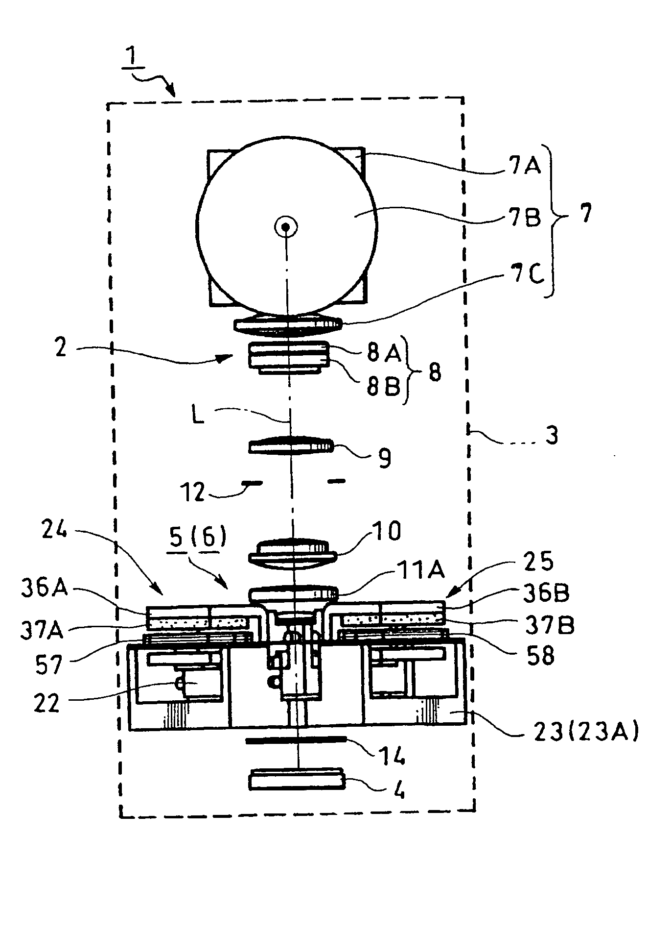
[0060] First, a lens device according to an embodiment of the present invention is explained. As shown in FIGS. 29 to 30, a lens device 1 representing a lens device of the present invention includes a lens system 2, a lens barrel 3, a CCD (solid-state imaging device) 4, an image stabilizer 5 and the like. The lens system 2 has five group lenses in which a plurality of lenses are disposed on the same optical axis L. The lens barrel 3 supports the lenses of this lens system 2 in a fixed or movable manner. The CCD 4, representing a specific example of an imager, is arranged on the optical axis L of the lens system 2 and is fixed to the lens barrel 3. The image stabilizer 5 is attached to the lens barrel 3 and stabilizes images of the lens system 2.

[0061] As shown in FIG. 29 and other figures, the lens system 2 in the lens device 1 includes a collapsible lens having a collapsible lens system formed of five group lenses 7 to 11 in which five lens groups are disposed on the same optical a...

second embodiment

[0121] FIGS. 8 to 9 show an image stabilizer 5A according to the present invention, in which magnetic materials 63 (64), 63A (64A), and 63B (64B) controlling the posture of a correcting lens 15 are provided outside a first coil 57 and a second coil 58. The magnetic material 63 (64) of steel or the like, or magnet-based magnetic materials 63A (64A) 63B (64B) are shaped like circular coins. Further, each of the magnet-based magnetic materials 63A (64A) and 63B (64B) is divided into the north and south poles by a polar boundary MB1 (MB2) extending in a diameter direction to divide the volume roughly in two.

[0122] As shown in FIG. 9A, each of the two magnetic materials 63 and 64 is placed in such a position that a center line MB0, which extends in a diameter direction to divide its volume roughly in two, is on a polar boundary MA1 (MA2) dividing the polarity of a magnet 37A (37B), when seen from a plane direction. Also the magnet-based magnetic materials 63A (64A) and 63B (64B) are disp...

third embodiment

[0130] FIGS. 10 to 11 show an image stabilizer 5B according to the present invention, in which four magnetic materials being magnetic members are provided, and the posture of a correcting lens 15 is controlled by the four magnetic materials 65, 66 (65A, 66A) (65B, 66B). Two magnetic materials 65 (66), 65A (66A) or 65B (66B) are provided for one coil 57 (58). The magnetic materials 65 (66), 65A (66A), and 65B (66B) are roughly-quadrilateral thin boards. Further, the magnetic material 65 (66) formed by a magnetic member of iron, steel or the like has a center line (imaginary line) MB0 linearly extending to divide the volume roughly in two. Also, as shown in FIGS. 11B and 11C, the magnetic materials 65A (66A) and 65B (66B) formed of magnets are divided into the north and south poles by a polar boundary MB1 (MB2) linearly extending to divide the volume roughly in two.

[0131] The magnetic materials 65 (66), 65A (66A), and 65B (66B) are provided on both sides outside the coil 57 (58) in th...


PUM


Abstract

An image stabilizer includes a driver having a coil and magnet, where a correcting lens on a moving frame is moved by the driver in a first direction perpendicular to an optical axis of a lens system and in a second direction perpendicular to the first direction and optical axis, and an optical axis of the correcting lens corresponds with the optical axis of the lens system. The coil and magnet are fixed to the moving frame and a supporting frame; the driver includes first and second coils for moving the correcting lens in the first and second directions, and a magnet applying magnetic force to those coils; and thrust generated from the first and second coils are directed in the first and second directions; a magnetic member attracted to or repelled by the magnet is provided in the vicinity of the first and second coils.

Description

CROSS REFERENCES TO RELATED APPLICATIONS [0001] The present invention contains subject manner related to Japanese Patent Application JP 2006-034173 filed in the Japanese Patent Office on Feb. 10, 2006, the entire contents of which being incorporated herein by reference. BACKGROUND OF THE INVENTION [0002] 1. Field of the Invention [0003] The present invention relates to an image stabilizer which stabilizes image blurred by vibration or the like at the time of shooting; a lens device which has the image stabilizer; and an imaging apparatus such as a digital still camera or video camera, incorporating the lens device. [0004] 2. Description of the Related Art [0005] In recent years, performance of an imaging apparatus such as a digital still camera and a video camera has been improved remarkably, and it became possible for anyone to easily shoot still pictures and moving pictures with high image quality and with high efficiency. Improved efficiency of such an imaging apparatus owes to h...

Claims


Application Information

Patent Timeline
Patent Type & Authority Applications(United States)
IPC IPC(8): H04N5/228
CPCG02B27/646G03B5/02H04N5/23287H04N5/23248H04N5/23258G03B5/04H04N23/68H04N23/6812H04N23/687
Inventor TAKAHASHI, TATSUYUKI
Owner SONY CORP
Why Eureka
Try Eureka