Mapping retinal function using corneal electrode array

a corneal electrode and retinal technology, applied in the field of local retinal analysis, can solve the problems of difficult to administer psychophysical tests to young patients or patients with very low vision, and the method also has significant drawbacks

Active Publication Date: 2007-08-16
THE BOARD OF TRUSTEES OF THE UNIV OF ILLINOIS
View PDF14 Cites 99 Cited by
  • Summary
  • Abstract
  • Description
  • Claims
  • Application Information

AI Technical Summary

Benefits of technology

[0015] In one aspect, the present invention provides an improved method for mapping spatial differences in retinal activity, using a full-field stimulus, especially one that is spatially invariant, and an electrode array in contact with a patient's cornea. This method is an improvement over multi-focal ERG and pattern ERG which both require specialized stimulus sources. A computational method is also provided for use in analyzing the bioelectric activity of the retina from potentials recorded at the cornea. This method provides an array of electrodes, and places the electrodes in electrical contact with the cornea. While illuminating the eye so as to cause retinal activity, measurements are made of the electrophysiological potentials at the cornea in response to the illumination with the array of electrodes. The method concludes by solving for retinal information based on the electrophysiological potentials made at the cornea.

Problems solved by technology

However, this psychophysical test has several drawbacks including difficulty in administering the test to young patients or patients with very low vision, and the fact that it measures quality of visual perceptions, and does not directly reflect function at the retina.
Further, such psychophysical tests cannot be administered to animals.
These methods also have significant drawbacks.
The mfERG takes several minutes to record, during which the subject must fixate on a small target, making it difficult to record from very young patients or patients with low central vision.
Further, the mfERG signal is not a true bioelectric signal, and physiological interpretation of the signal remains a challenge.
As mentioned, eye diseases often result in localized dysfunction of the retina.
These predicted spatial differences in retinal activity are irreconcilable with current knowledge of distributed retinal activity, and most likely reveal the serious limitations of the oversimplified model.
One drawback of existing systems is that they are designed to infer local physiological activity in the retina from biopotential recordings use single electrodes, or single bipolar pairs of electrodes, located on the eye surface, in combination with a spatially-variant optical stimulus (e.g. a focal spot, an array of hexagons, a checkerboard).
This method is limited in several significant ways.
First, stimulus dynamics inherent to the mfERG technique limit measurements to primarily cone-pathways activity.
Second, the output of the mfERG system is a mathematical abstraction of the recorded activity of the retina, which has limited interpretation at present, and which can thus be misinterpreted or over-interpreted.
In addition, the mfERG test is difficult to administer to patients with low vision or to small children because the patient must fixate on a small visual target for several minutes of continuous data acquisition.
Additional minor limitations include the restricted area of retinal evaluation (typically covering the central 50 degrees of the field of vision) and the relatively high cost which restricts access to the testing procedure.
There is no known prior art system involving a contact lens electrode array.
Also, there is no known prior art system involving the use of biopotentials recorded from multiple locations on the cornea, or from the cornea plus the sclera and / or face and / or scalp, to infer spatial differences in physiological activity of the retina.

Method used


Image

  • Mapping retinal function using corneal electrode array
  • Mapping retinal function using corneal electrode array
  • Mapping retinal function using corneal electrode array

Examples


Embodiment Construction

[0040] The invention described herein is, of course, susceptible of embodiment in many different forms. Shown in the drawings and described hereinbelow in detail are preferred embodiments of the invention. It is understood, however, that the present invention in an exemplification of the principles of the invention and does not limit the invention to the illustrated embodiments. For ease of description, different arrangements embodying the present invention are described hereinbelow in their usual assembled position as shown in the accompanying drawings, and terms such as upper, lower, horizontal, longitudinal, etc. may be used herein with reference to this usual position. However, the arrangements may be manufactured, transported, sold or used in orientations other than that described and shown herein.

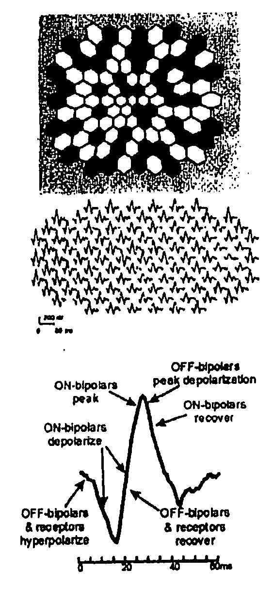
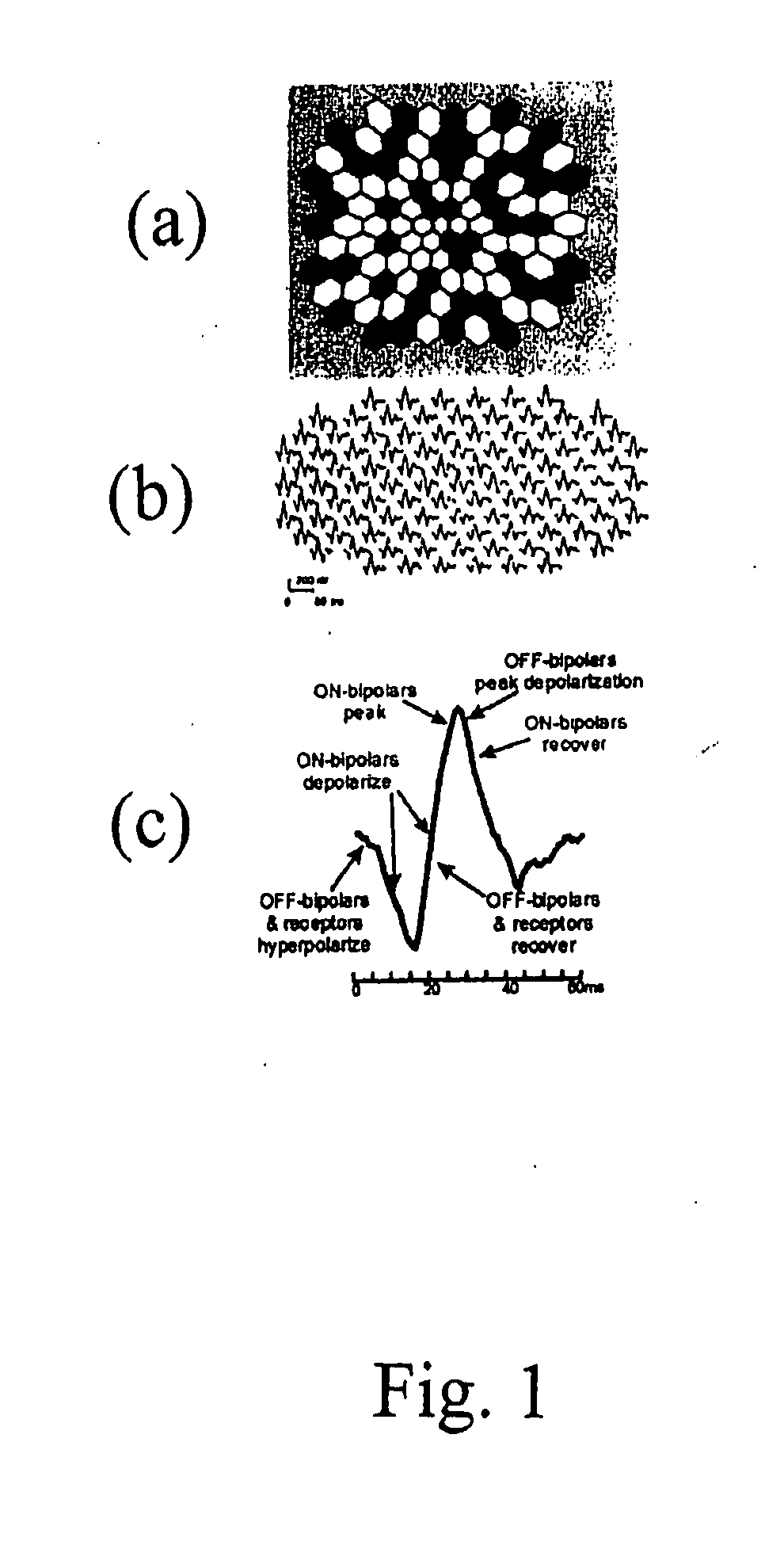
[0041] New systems and techniques are provided for measuring local activity in the retina and, if desired, may be used with existing techniques. A brief review of electroretinography...


PUM


Abstract

A system and method for obtaining information about the spatial distribution of photoreceptor activity and neural activity in the retina using simultaneously recorded multiple biopotential signals. The information thus gathered is used to assess retinal dysfunction due to trauma or disease. The biopotential signals are recorded from the surface of the eye and head using a plurality of electrodes, including those integral to a contact lens. The biopotential signals are recorded before, during and after the presentation of an optical stimulus to the subject eye. The recorded biopotential signals are then analyzed and interpreted to reveal the distribution of photoreceptor activity and neural activity across the retina. The analysis and interpretation of the biopotential signals is quantitative, and makes use of an electromagnetic model of the subject eye. The subject may be animal or human.

Description

CROSS-REFERENCE TO RELATED APPLICATION [0001] This application claims the benefit of U.S. Provisional Application for Patent Ser. No. 60 / 774,097, filed on Feb. 16, 2006, which is incorporated herein by reference.FIELD OF THE INVENTION [0002] The present invention relates to local retinal analysis and, in particular, to a system and method for mapping spatial differences in retinal activity using a corneal electrode array to analyze local retinal dysfunction and the presence of eye disease. DESCRIPTION OF THE RELATED ART [0003] Measurement of the function of the retina, either directly or indirectly, is a central component in diagnosing, assessing and monitoring the progression of dysfunction due to disease or trauma. Indirect measurements of the function of the retina include psychophysical tests, e.g. the Humphrey Visual Field test. Direct measurements include electrophysiological measurements such as the electroretinogram (ERG). [0004] Dysfunction of the retina due to disease or t...

Claims


Application Information

Patent Timeline
Patent Type & Authority Applications(United States)
IPC IPC(8): A61B3/10
CPCA61B5/0496A61B5/398
Inventor HETLING, JOHN R.BAN, TAMASRAHMANI, SAFA
Owner THE BOARD OF TRUSTEES OF THE UNIV OF ILLINOIS
Why Eureka
Try Eureka