Anti-Collision Warning System for Marine Vehicle and Anti-Collision Analysis Method
an anti-collision and marine vehicle technology, applied in the direction of reradiation, distance measurement, instruments, etc., can solve the problems of high vulnerability of ships, poor control of collision risk, and environmental consequences of collisions
- Summary
- Abstract
- Description
- Claims
- Application Information
AI Technical Summary
Benefits of technology
Problems solved by technology
Method used
Image
Examples
first embodiment
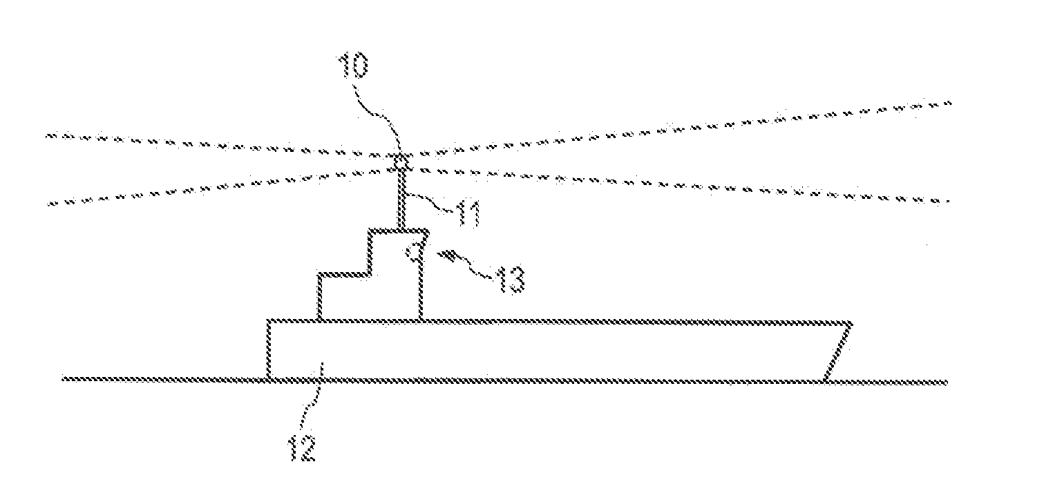
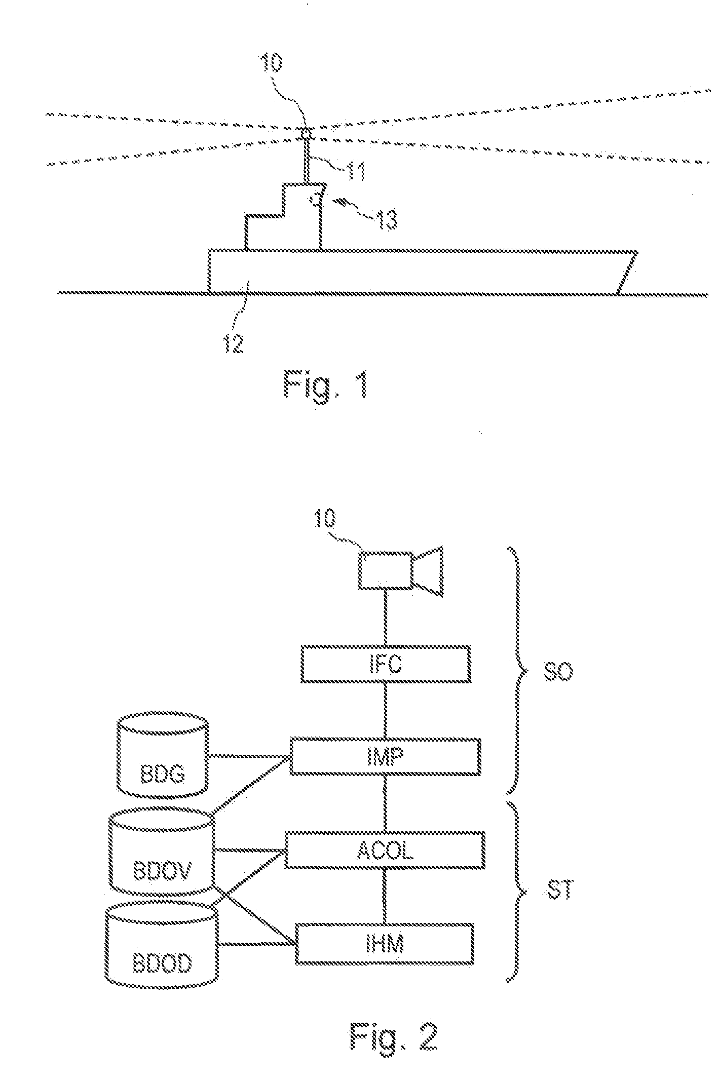
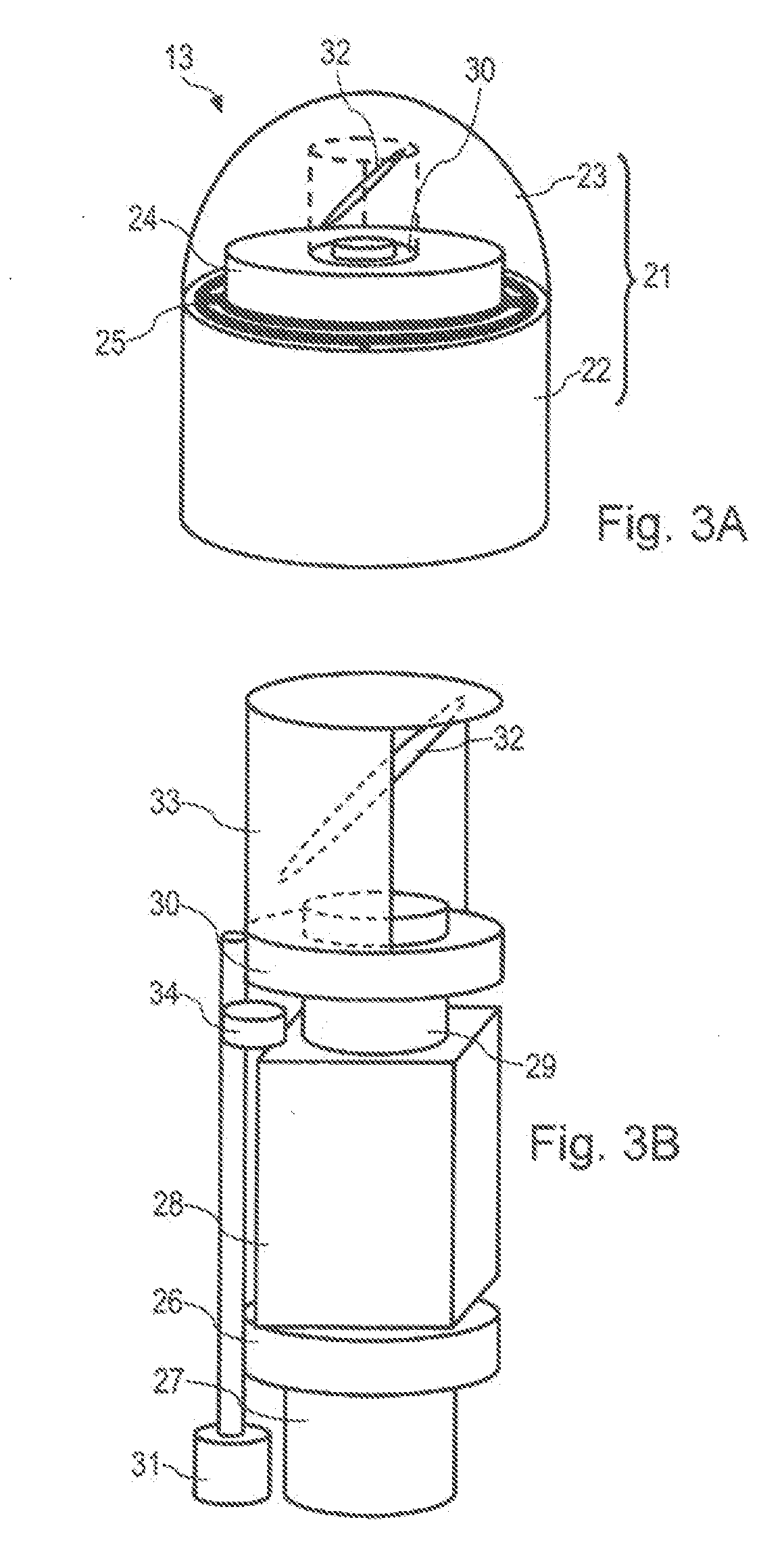
[0052] In the first embodiment shown in FIG. 3A and 3B, the optical sensor 10 comprises a video camera the optical field of which can be oriented to cover the horizon by rotation. The video camera is mounted onto a platform stabilized by a gyroscope. The sensor 10 includes a housing 21 made up of a base 22 used as a stand and a transparent dome shield 23, a stabilized tank 24 mounted onto a stabilization device made up of a gimbal 25 and of a gyro wheel 26 driven by an electric motor 27, a video camera 28 fixed onto the stabilized tank and bearing a lens 29 facing the zenith, and a rotating assembly 30 mounted in the stabilized tank driven by a vertical axis rotation motor 31 placed in the bottom of the stabilized tank, and bearing in its upper part a mirror 32 and a sun screen 33. The 45°-orientation of the mirror enables the optical axis of the mirror 32 to scan a horizontal plane by the rotation of the rotating assembly 30, the rays being reflected by the mirror 32 so as to reach...
second embodiment
[0059] In a second embodiment shown in FIGS. 4A and 4B, the optical sensor 10 comprises a single-line video camera that can be oriented, mounted onto a fixed stand.
[0060] More precisely, the optical sensor 10 includes a cylindrical housing 41 fixed onto the masts of the ship, a rotating assembly 42 held in the housing 41 by ball bearings 43 and driven by a vertical axis rotation motor 44 placed at the bottom of the housing, the upper part of the rotating assembly comprising a cylindrical protection cover 45 provided with a rectangular window 49 that enables the optic rays to pass through the cover to reach the lens, and a digital video camera 46 fixed onto the rotating assembly 42 and the single-line detecting element 47 of which is offset above the body of the video camera; the detecting element typically comprises from 512 to 8,192 light-sensitive basic cells disposed in a vertical line. The optical sensor also includes a lens 48, having an angular opening typically of 30 to 55°, ...
third embodiment
[0069] In a third embodiment shown in FIGS. 5A and 5B, the optical sensor 10 comprises a set of fixed video cameras. More precisely, the optical sensor 10 includes a housing 61 fixed onto the superstructure of the ship and comprising a glass opening 62, one or more digital video cameras 63 (typically four) fixed onto the housing 61, and one lens 64 for each video camera 63, the set of lenses being disposed in such a way that the areas they scan cover a substantial portion of the horizon (typically 187°). The optical sensor 10 also includes a connection and multiplexing device 65 enabling the images coming from all the video cameras to be processed simultaneously. This device can integrate an integrated circuit card performing part of the image processing.
[0070] In this third embodiment, the resolution of the images is linked to the platform movements of the carrier ship. Typically, on a large ship having a rolling motion limited to + / −10°, using video cameras having a definition of ...
PUM
 Abstract
Description
Claims
Application Information
 - R&D
- Intellectual Property
- Life Sciences
- Materials
- Tech Scout
- Unparalleled Data Quality
- Higher Quality Content
- 60% Fewer Hallucinations
Browse by: Latest US Patents, China's latest patents, Technical Efficacy Thesaurus, Application Domain, Technology Topic, Popular Technical Reports.
© 2025 PatSnap. All rights reserved.Legal|Privacy policy|Modern Slavery Act Transparency Statement|Sitemap|About US| Contact US: help@patsnap.com


