Cryptographic unit and method for operating a cryptographic unit

Active Publication Date: 2007-08-16
INFINEON TECH AG
View PDF5 Cites 63 Cited by
  • Summary
  • Abstract
  • Description
  • Claims
  • Application Information

AI Technical Summary

Benefits of technology

[0024] It is the object of the present invention to provide a possibility to provide a cryptographic un

Problems solved by technology

So-called fault attacks (FA) represent a serious threat for the implementation of cryptographic algorithms, irrespective of whether the algorithm is implemented in software or as hardware module.
While asymmetric methods, such as RSA, may be protected in a relatively simple way by well-known published measures, it is extremely difficult to protect symmetric encryption methods, such as the advanced encryption standard (AES) or the DES (data encryption standard).
These faults result in wrong encryption or decryption results.
If, however, a higher security level is necessary, the occurrence of any multiple bit faults has to be detected.
Thus, there are no general solutions known today for the case of injected multiple bit faults except trivial redundancy as: a) multiple repetition of the encryption (or decryption) and comparison of the results (time redundancy).
In any case, this method results approximately in halving the data throughput.
However, one cannot rule out in this case that more sophisticated cryptographic analysis methods may be successful even here.
However, the double implementation, for example, requires a high hardware effort and still contains security gaps, because in this case the comparison may, for example, also be a target of the attack.
If injected faults in the comparator lead to the non-detection of the inequality of results, a wrong result may still be output.
Furthermore, the identical duplication and the comparison have the weakness that the probability for “equal faults” in both data paths is not negligible and thus sufficiently faulty results are not detected and a successful attack becomes possible.
The fault detection by parity bits has the disadvantage that only an uneven number of faulty bits

Method used


Image

  • Cryptographic unit and method for operating a cryptographic unit
  • Cryptographic unit and method for operating a cryptographic unit
  • Cryptographic unit and method for operating a cryptographic unit

Examples


Embodiment Construction

[0075] In the following description of the figures, equal or similar elements are referred to by equal or similar reference numerals, a repeated description of these elements being omitted.

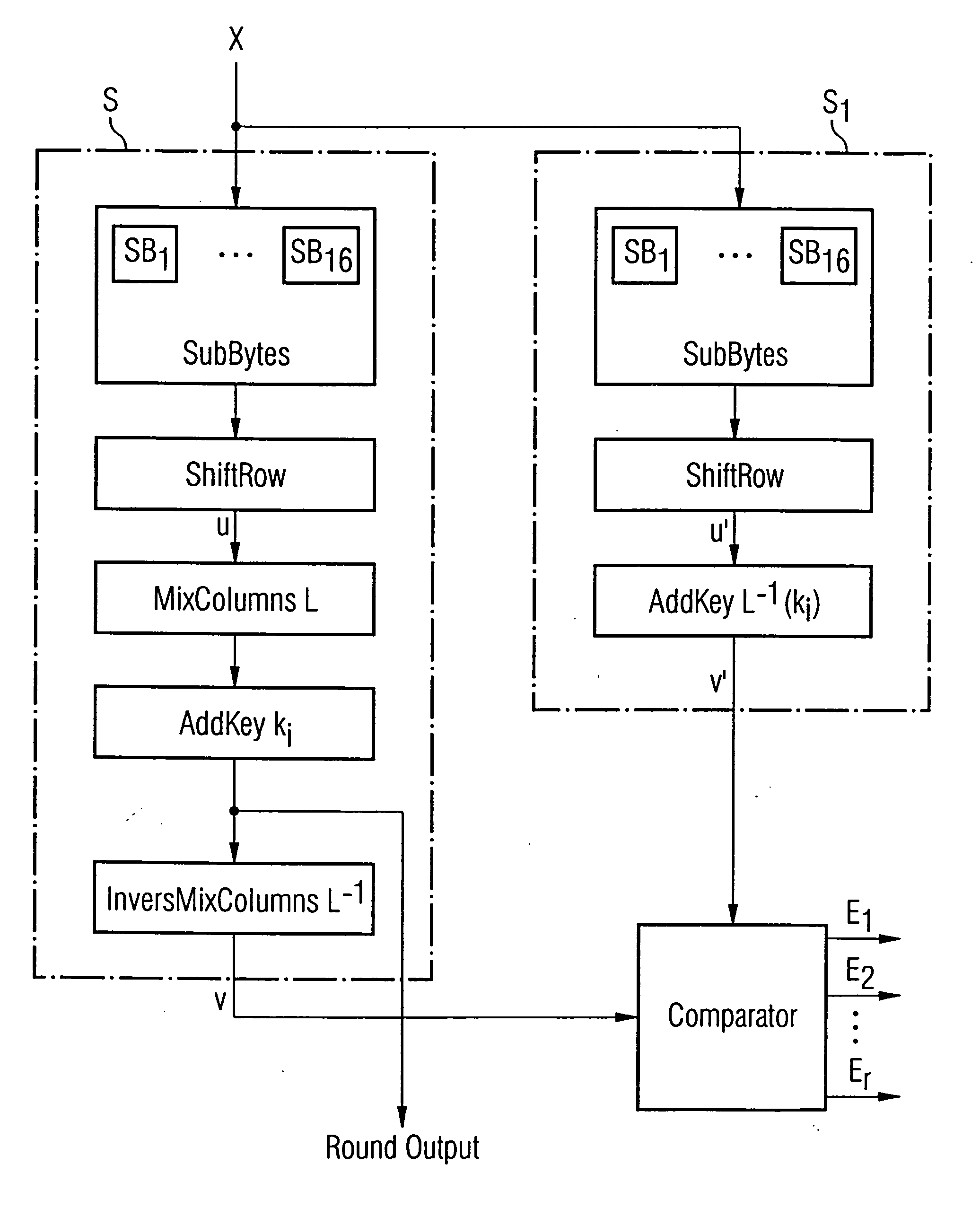
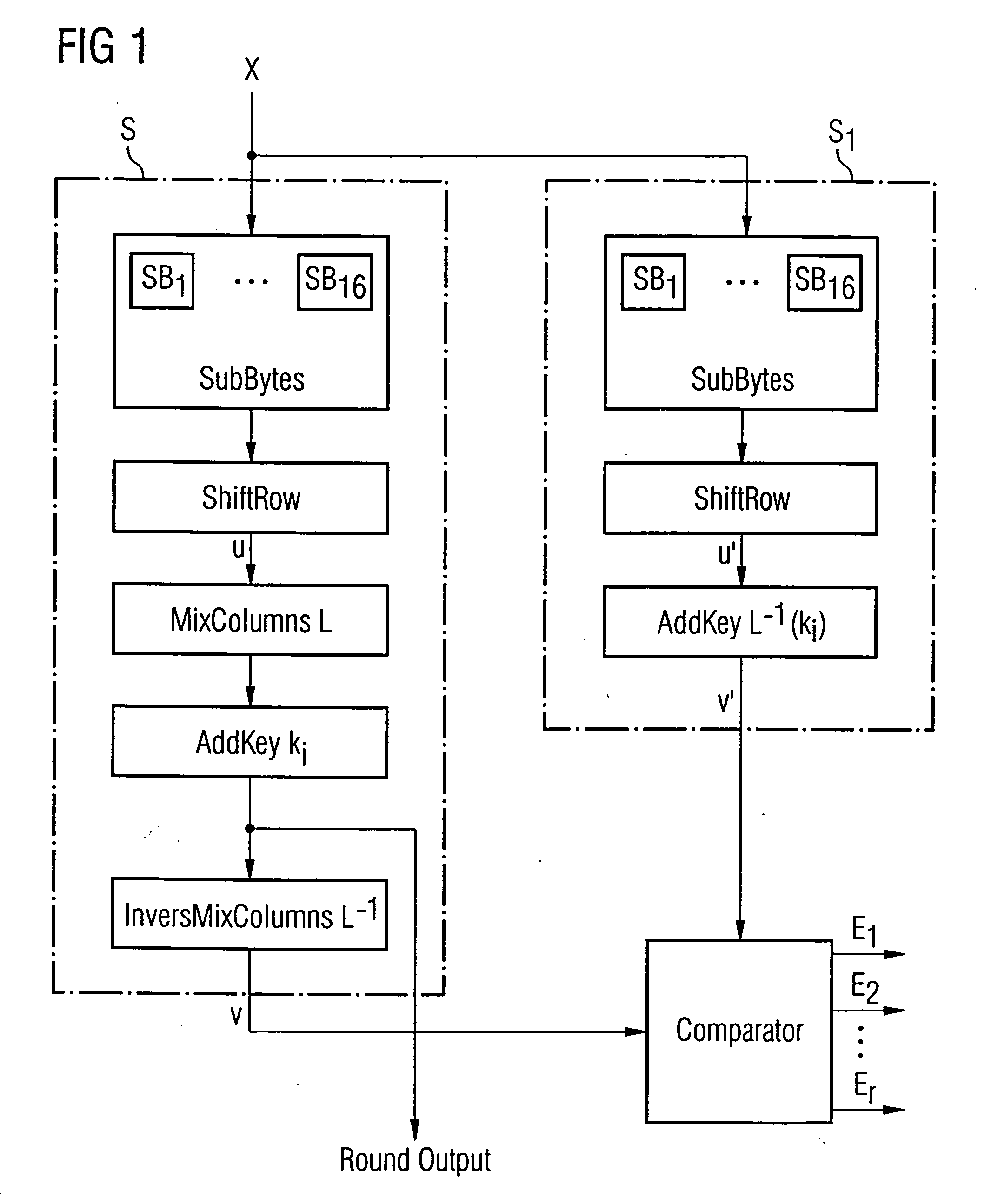
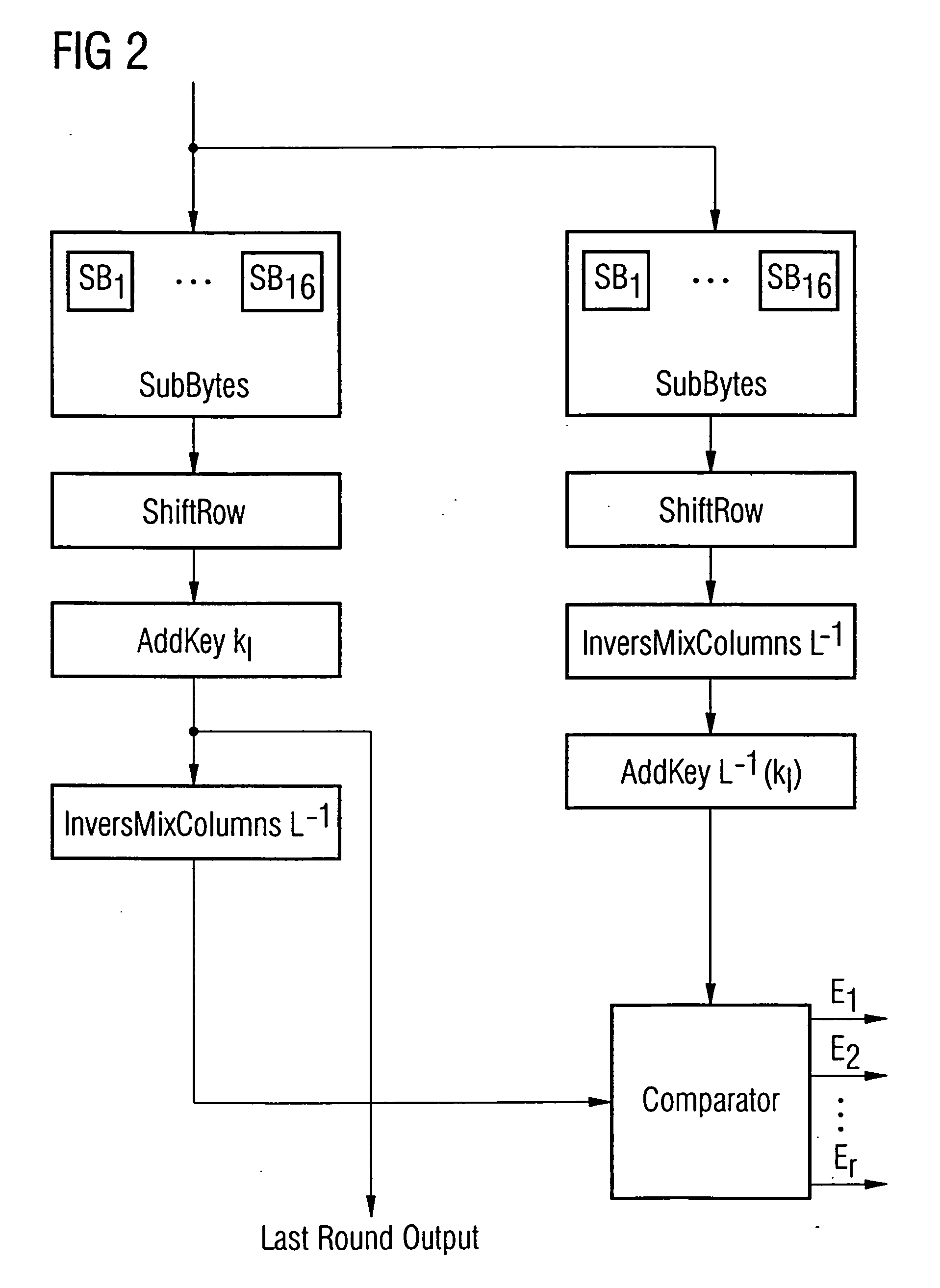
[0076] Initially it is to be noted that the encryption of the data by the AES algorithm is performed in a predetermined number of successive rounds depending on the key length, which are consecutively numbered. Thus, the number of the rounds in the AES is, for example, 10, 12 or 14, respectively (with the numbers 1 to 10, 12 or 14, respectively), depending on a key length of 128, 196 or 256 bits, respectively. In the rounds l to the next to last round, there are performed the operations SubBytes in S-boxes, ShiftRow, MixColumns and AddKey (or AddRoundKey), in the last round the operation MixColumns is omitted. If, for example, we assume a word width of n=128 bits, the operation SubBytes is realized by 16 S-boxes each having an input word width of 8 bits and an output word width of 8 bits. The ope...


PUM


Abstract

A cryptographic unit includes a first processing unit for determining an output signal on the basis of the AES algorithm and for determining a first comparison signal, a second processing unit for determining a second comparison signal, and a release unit for providing the output signal, wherein the release unit is designed to perform a defense measure against an external tapping of the output signal when the first comparison signal is not related to the second comparison signal in a predetermined relationship. The first comparison signal is determined in a different way as compared to the second comparison signal, so that, in the case of the injection of faults into the cryptographic unit, these faults may be detected very easily.

Description

CROSS-REFERENCE TO RELATED APPLICATION [0001] This application claims priority from German Patent Application No. 10 2004 062 825.4, which was filed on Dec. 27, 2004, and is incorporated herein by reference in its entirety. BACKGROUND OF THE INVENTION [0002] 1. Field of the Invention [0003] The present invention relates to the technical field of cryptography and the present invention particularly refers to the detection of so called fault attacks of cryptographic units. [0004] 2. Description of the Related Art [0005] So-called fault attacks (FA) represent a serious threat for the implementation of cryptographic algorithms, irrespective of whether the algorithm is implemented in software or as hardware module. [0006] While asymmetric methods, such as RSA, may be protected in a relatively simple way by well-known published measures, it is extremely difficult to protect symmetric encryption methods, such as the advanced encryption standard (AES) or the DES (data encryption standard). W...

Claims


Application Information

Patent Timeline
IPC IPC(8): H04L9/00
CPCH04L9/004H04L2209/12H04L9/0631
Inventor GAMMEL, BERNDTBOCK, HOLGERGOESSEL, MICHAEL
Owner INFINEON TECH AG
Why Eureka
Try Eureka