Reformer and fuel cell system control and method of operation

a fuel cell and system control technology, applied in the direction of sustainable manufacturing/processing, instruments, physical/chemical process catalysts, etc., can solve the problems of hydrogen pressure exceeding safety limits, pressure dropping below the recommended limits, and the output pressure of the membrane will generally vary too much, so as to achieve the effect of lowering the current output of the fuel cell

Inactive Publication Date: 2007-08-16
GENESIS FUEL TECH INC
View PDF9 Cites 24 Cited by
  • Summary
  • Abstract
  • Description
  • Claims
  • Application Information

AI Technical Summary

Benefits of technology

[0026] A benefit of the control system and methodology described herein is the simple integration of a fuel cell system with the purification reformer. The control of the reformer as described does not require any external input or flow transducer measurements; the sensing of the output hydrogen pressure and the internal temperatures of the reformer provide the needed information. Adjustment of the DC-DC converter to lower the current output of the fuel cell can be done with a DC-DC converter controller that receives hydrogen pressure and fuel cell voltage information. Alternatively, a system controller can control both the reformer and the DC-DC converter. In all cases, the control of the reformer at a sufficient minimum temperature is adequate to allow for transients and surge loading, rather than the use of a ...

Problems solved by technology

However, the output pressure of the membrane will generally vary too widely for use with a typical fuel cell; at low hydrogen output, the hydrogen pressure will generally exceed the safety limits o...

Method used


Image

  • Reformer and fuel cell system control and method of operation
  • Reformer and fuel cell system control and method of operation
  • Reformer and fuel cell system control and method of operation

Examples


experiment 1

[0050] Experiment 1

[0051] A Genesis Fueltech model GT-8 hydrogen purification reformer was used to supply hydrogen to an Avista Labs (Spokane, Wash.) SR-12 fuel cell. The reformer as tested was capable of supplying over 6 standard liters of hydrogen per minute. The reformer control system utilized an industrial programmable ladder logic controller coupled to a hydrogen output pressure transducer, thermocouples for measuring the temperature exiting the catalyst bed and palladium-alloy membrane, and an AC solenoid pump for injecting pressurized methanol / water mix into the reformer. The pump was controlled by periodically turning it on for short periods to charge the reformer with a pulse of methanol / water. The proprietary reforming catalyst required a temperature of approximately 360-425° C. for high conversion of the methanol and water into hydrogen and carbon dioxide. The minimum hydrogen output pressure setpoint was 3 psig, with an upper limit controlled by a pressure regulator. Th...

experiment 2

[0055] Experiment 2

[0056] A Genesis Fueltech GT-8, as described above, was connected to an Hcore-500 fuel cell (H-Power, Inc.). The output of the fuel cell was tested with an adjustable load bank. Once the reformer was warmed up, the fuel cell was brought on-line, using the hydrogen produced by the reformer. In the minimal load condition, the catalyst temperature was maintained at a minimum of about 360-380° C. by increasing the pump rate to prevent cooling below this temperature.

[0057] Once the fuel cell was ready, the load was changed from 0 to 400 watts with a unit step increase. The hydrogen pressure momentarily dropped below 3 psig, but was restored within approximately 3 seconds as the reformer controller increased the pump rate for the methanol / water feedstock. The reformer was able to maintain the 400 watt consumption rate in the steady state, since the catalyst bed was kept above the minimum temperature needed for high production. The calculated hydrogen consumption at the...

experiment 3

[0058] Experiment 3

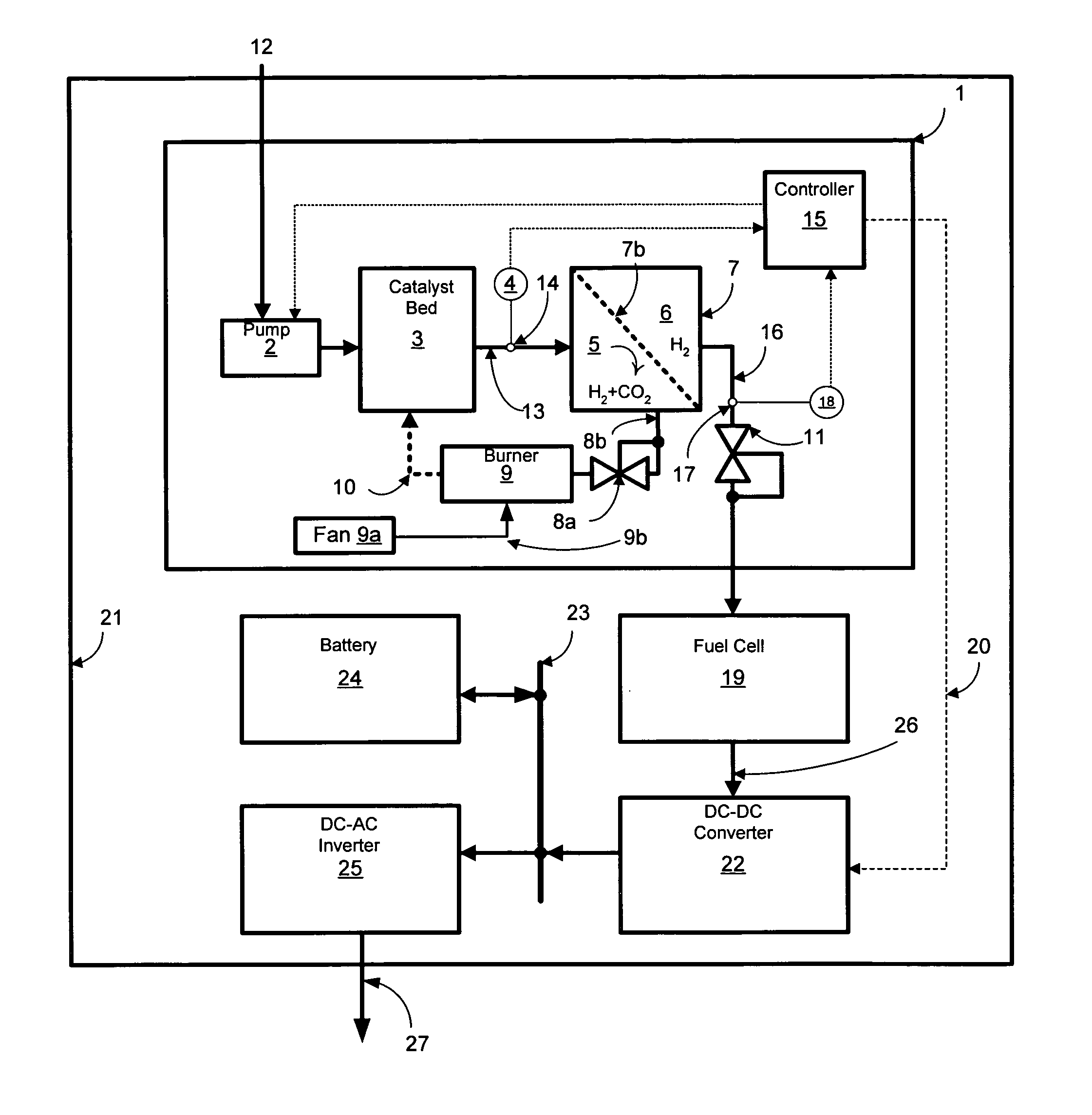
[0059] A Genesis Fueltech model 20L reformer, rated at an output of 20 standard liters per minute of hydrogen at a minimum output pressure of 5 psig, was configured with an output pressure regulator and flow meter for transient testing. In this particular case, referring to FIG. 1, the output pressure regulator 11 was physically external to reformer enclosure 1, with the hydrogen vented to ambient rather than traveling to a fuel cell. Pressure sensing 18 for control of the reformer was internal to reformer enclosure 1, sensing the pressure on pressure regulator input line 16. The external pressure regulator (Marshall Gas Controls, Inc., model 350) was set to an output pressure of 5 psig, and the flow meter (Advanced Specialty Gas Equipment, model VFM7965B-3B) was set for a flow of 20.5 slm of hydrogen. The output flow rate was verified with water displacement testing.

[0060] The reformer was set with zero hydrogen output flow and allowed to stabilize. The controll...


PUM

PropertyMeasurementUnit
Temperatureaaaaaaaaaa

Abstract

A fuel cell system includes a reformer producing hydrogen from fuel, a regulator for regulating the output pressure of the produced hydrogen, a fuel cell utilizing the produced hydrogen, a pressure sensor for monitoring the pressure of the hydrogen upstream of the pressure regulator, a temperature sensor for monitoring at least one temperature within the reformer, a pump for introducing the fuel into the reformer, a first controller for controlling the output current of the fuel cell, and a second controller for controlling at least the fuel introduction rate into the reformer. The introduction rate of the fuel is responsive to output hydrogen pressure from the reformer in order to maintain at least one temperature within the reformer above a minimum level, as well as maintaining the pressure of the delivered purified hydrogen above a set pressure. Further, the output current of the fuel cell is reduced responsive to the pressure of the purified hydrogen in order to maintain a minimum hydrogen pressure to the fuel cell.

Description

CROSS REFERENCE TO RELATED APPLICATION [0001] This application claims priority to U.S. Provisional Patent Application No. 60 / 705,234, filed Aug. 3, 2005.FIELD OF THE INVENTION [0002] This invention relates to control systems for fuel cells and hydrogen-producing fuel processors, and methods for operating the control system. Specifically, the invention describes the operation of a hydrogen-producing reformer coupled to a fuel cell, where the operation of the reformer and fuel cell is such that a hydrogen feed pressure to the fuel cell is maintained above a minimum desired point, voltages within the fuel cell are maintained above a desired point, and where the reformer is maintained at a temperature such that a minimum hydrogen output pressure may be maintained during transient operation from low to high output. BACKGROUND OF THE INVENTION [0003] Hydrogen-powered fuel cells offer tremendous promise for providing electrical power in a variety of existing and new applications. For conti...

Claims


Application Information

Patent Timeline
IPC IPC(8): H01M8/04H01M8/06B01J19/00B01J8/02
CPCC01B3/323Y02E60/50C01B3/501C01B11/024C01B2203/0233C01B2203/0405C01B2203/0475C01B2203/066C01B2203/0811C01B2203/0822C01B2203/0827C01B2203/1223C01B2203/1229C01B2203/1619C01B2203/1633C01B2203/1638C01B2203/169H01M8/04089H01M8/04201H01M8/04373H01M8/04425H01M8/04738H01M8/04753H01M8/0491H01M8/0618C01B3/384Y02P20/10
Inventor DEVRIES, PETER DAVID
Owner GENESIS FUEL TECH INC
Why Eureka
Try Eureka