Eureka AIR delivers breakthrough ideas for toughest innovation challenges, trusted by R&D personnel around the world.

Electrode for fuel cell, fuel cell, and method of preparing electrode for fuel cell

Inactive Publication Date: 2007-08-16
SAMSUNG SDI CO LTD +2
View PDF4 Cites 7 Cited by
  • Summary
  • Abstract
  • Description
  • Claims
  • Application Information

AI Technical Summary

Benefits of technology

[0010] According to an aspect of the present invention, there is provided a fuel cell that includes an electrolyte membrane prepared by impregnating a basic polymer with an acid and operates at high temperature under non-humid conditions. The fuel cell includes a catalyst layer capable of preventing the inhibition of gas diffusion by water formation and capable of preventing the inhibition of gas diffusion by an electrode catalyst being covered with the acid.

Problems solved by technology

However, at high temperature, an electrolyte membrane loses liquid and dries up.
However, a large amount of the liquid phosphoric acid contained in an electrode inhibits gas diffusion.

Method used


Image

  • Electrode for fuel cell, fuel cell, and method of preparing electrode for fuel cell
  • Electrode for fuel cell, fuel cell, and method of preparing electrode for fuel cell
  • Electrode for fuel cell, fuel cell, and method of preparing electrode for fuel cell

Examples


embodiments

[0036] Hereinafter, embodiments of the present invention will be described with reference to the attached drawings.

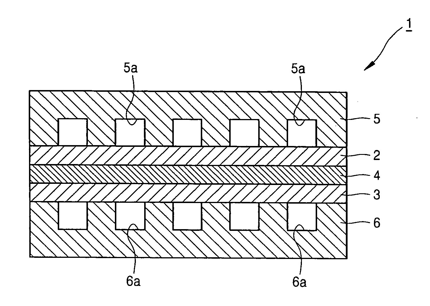
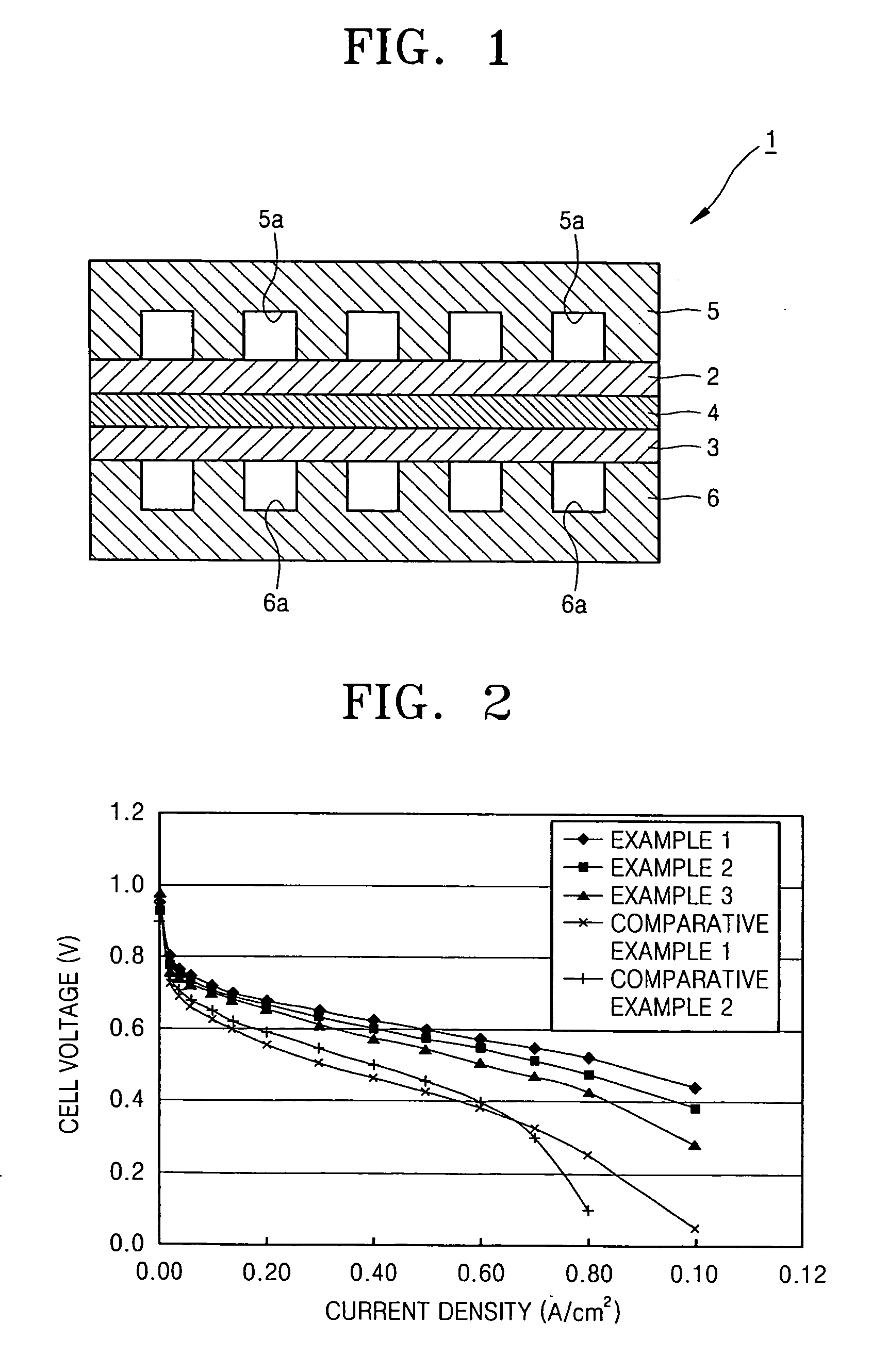
[0037]FIG. 1 is a cross-sectional view of a fuel cell 1 according to an embodiment of the present invention.

[0038] Referring to FIG. 1, the fuel cell 1 includes an oxygen electrode 2, a fuel electrode 3, a proton-conductive solid polymer electrolyte membrane 4 interposed between the oxygen electrode 2 and the fuel electrode 3 (hereinafter referred to as an electrolyte membrane 4), an oxidant bipolar plate 5 having an oxidant channel 5a outside the oxygen electrode 2, and a fuel bipolar plate 6 having a fuel channel 6a outside the fuel electrode 3. The fuel cell operates in a temperature range of 100-200° C.

[0039] The oxidant bipolar plate 5 and the fuel bipolar plate 6 are formed of a conductive metal or the like, and respectively contact the oxygen electrode 2 and the fuel electrode 3 to act as a current collector. The oxidant bipolar plate 5 and the fuel bipolar pl...

example 1

[0059] An electrode according to an embodiment of the present invention was prepared in the following manner. 1.5 g of a platinum-containing catalyst in which 50% of the platinum was supported by carbon (Vulcan XC72) was measured while contained in a beaker, and then 3.0 g of N-methylpyrrolidone (NMP) as a solvent was added thereto and mixed at room temperature for one hour until a homogeneous solution of the catalyst and the solvent was attained.

[0060] Then, a 10% by weight of a poly(vinylidenefluoride) solution was prepared by dissolving a KF polymer (produced from Kureha) in NMP as a solvent, and the poly(vinylidenefluoride) solution was mixed with the catalyst-containing solution. In this case, the poly(vinylidenefluoride) solution was slowly dropped into the catalyst-containing solution until the amount of poly(vinylidenefluoride) was 2.5 parts by weight based on 1 part by weight of the catalyst, and the result was mixed for one hour.

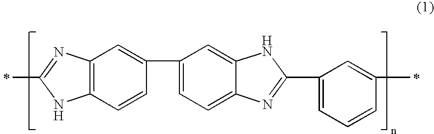
[0061] Next, a 1% by weight of a polybenzi...

example 2

[0063] An electrode for a fuel cell according to Example 2 was produced in the same manner as in Example 1, except that the amount of poly(vinylidenefluoride) was 1.25 parts by weight and the amount of polybenzimidazole was 6.25 parts by weight, based on 1 part by weight of the catalyst.


PUM


Abstract

A fuel cell that operates at high temperature under non-humid conditions using an electrolyte membrane prepared by impregnating a basic polymer with an acid and a method of producing an electrode for a fuel cell, the fuel cell includes a catalyst layer electrode that can prevent the inhibition of gas diffusion due to generated water and the inhibition of gas diffusion due to an electrode catalyst being covered with an acid that leaks from the electrolyte membrane impregnated with the acid. The electrode includes a catalyst layer including a platinum-containing catalyst, a basic polymer, and a hydrophobic binder.

Description

BACKGROUND OF THE INVENTION [0001] 1. Field of the Invention [0002] An aspect of the present invention relates to an electrode for a fuel cell, a fuel cell, and a method of preparing the electrode for a fuel cell, and more particularly, to an electrode for a fuel cell including an electrode catalyst layer suitable for operating at a high temperature under non-humid conditions, and a method of preparing the electrode for a fuel cell. [0003] 2. Description of the Related Art [0004] Polymer electrolyte fuel cells (PEFCs), which include polymer electrolyte membranes as an electrolyte, operate at relatively low temperature and can be miniaturized. Due to these advantages, PEFCs are expected to be used as power sources for electric cars and in domestic distribution energy generating systems. Conventionally, a perfluorocarbonsulfonic acid-based polymer membrane, such as NAFION®, is used as a polymer electrolyte membrane for a PEFC. [0005] The perfluorocarbonsulfone-based polymer membrane n...

Claims


Application Information

Patent Timeline
IPC IPC(8): H01M4/86H01M8/10H01M4/88H01M8/02
CPCH01M4/8652H01M4/8668H01M4/8807H01M4/8828Y02E60/521H01M8/04291H01M8/1004H01M2008/1095H01M2300/0082H01M4/92Y02E60/50
Inventor SONAI, ATSUOYANO, MASAYATABATA, KATSUYUKINAKATO, KUNIHINO
Owner SAMSUNG SDI CO LTD
Why Eureka
Eureka Blog
Learn More