Testing for Leaks in a Two-Phase Liquid Cooling System

a liquid cooling system and leak detection technology, applied in the direction of refrigeration machines, structural/machine measurement, refrigeration safety arrangements, etc., can solve the problems of reducing the thermal performance of the system, affecting the cooling efficiency of the system, so as to achieve the effect of more efficient cooling

Inactive Publication Date: 2007-08-23
ISOTHERMAL SYST RES
View PDF29 Cites 43 Cited by
  • Summary
  • Abstract
  • Description
  • Claims
  • Application Information

AI Technical Summary

Benefits of technology

[0009]A technique is thus provided for detecting leaks in a return path in a two-phase liquid cooling system or any other path in the system in which, during normal operation of the system, the path is at a pressure below atmospheric pressure. To test for leaks in such a path, the pressure in the path is temporarily raised, causing coolant to be expelled through any leaks in the path. A coolant sensor can then be used to detect any leaks. Once the testing is completed, the path is returned to normal operation for more efficient cooling.

Problems solved by technology

As air cooling heat sinks continue to be pushed to new performance levels, so has their cost, complexity, and weight.
Leaks in the system can throw these parameters off balance, as leaks can result in non-condensable air added to the system or coolant loss from the system.
The result of leaks is often to degrade the thermal performance of the system.
If the detector is located near the vicinity of a leak in which coolant is leaking from the system, the detector will indicate the presence of the coolant and, therefore, a leak in the system.
For this reason, any leaks in the return path generally result in air leaking into the system rather than coolant leaking out of the system.
The refrigerant detector—or any kind of external sensor—is not helpful in such a case.

Method used


Image

  • Testing for Leaks in a Two-Phase Liquid Cooling System
  • Testing for Leaks in a Two-Phase Liquid Cooling System
  • Testing for Leaks in a Two-Phase Liquid Cooling System

Examples


Embodiment Construction

Two-Phase Cooling System with Active Venting

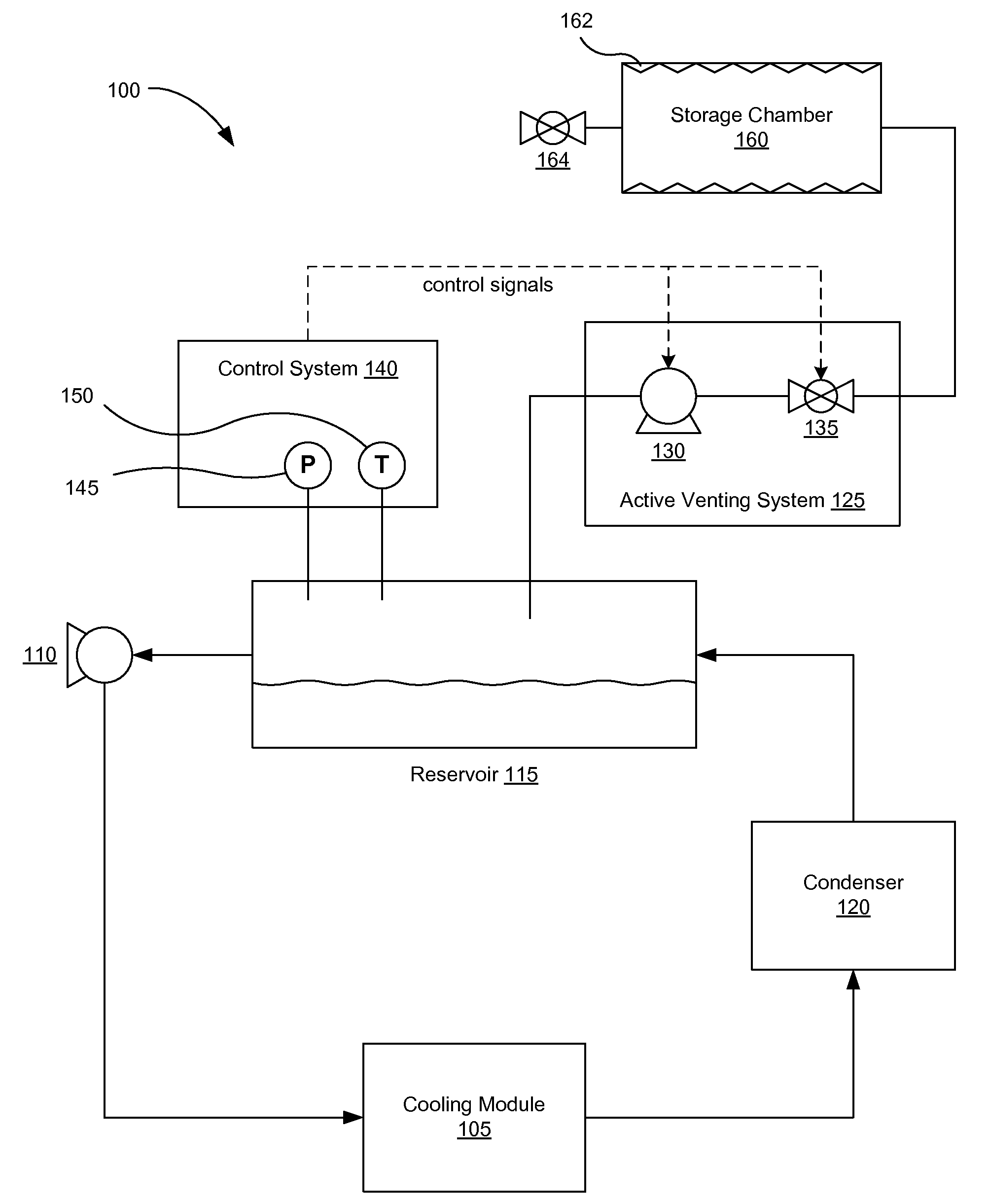
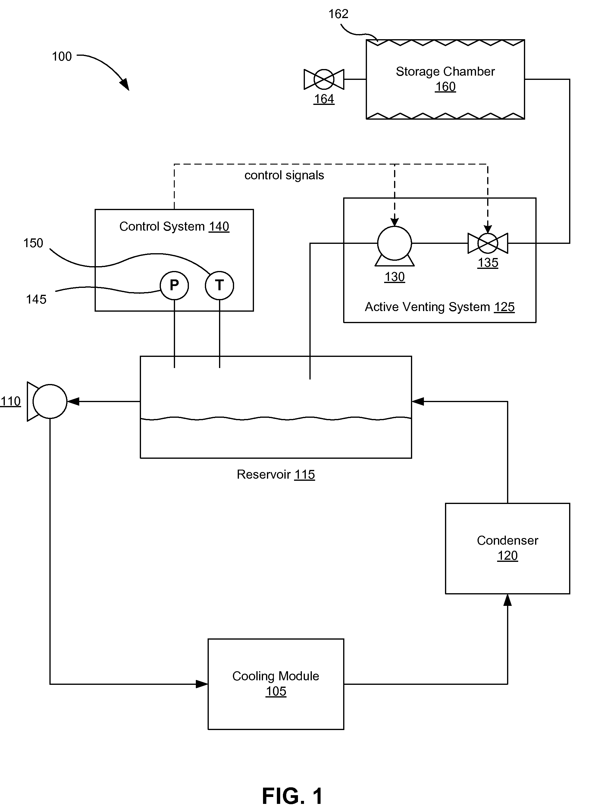
[0025]FIG. 1 illustrates one embodiment of a two-phase liquid cooling system 100 with active venting capabilities. The liquid cooling system 100 includes at least one cooling module 105, a pump 110, a reservoir 115, and a condenser 120. The pump 110 pressurizes a supply of liquid coolant from the reservoir 115 and delivers the liquid coolant to the cooling module 105. The cooling module 105 places the liquid coolant in thermal contact with a heat-producing device (not shown), such as but not limited to computer processors, blade servers, circuit boards, memory, video cards, power devices, and the like. In the cooling module 105, heat from the heat-producing device transforms at least a portion of the liquid coolant into a vapor phase fluid. The cooling fluid is transferred to a condenser 120, which removes heat and condenses the vapor phase fluid back into the liquid phase and delivers it to a reservoir 115. The liquid coolant can then be ...


PUM


Abstract

A two-phase liquid cooling system includes an active venting system for regulating an amount of non-condensable gas within the cooling system. Various venting structures may be used to remove gases from the cooling system, some of which are designed to remove the non-condensable gases and avoid removing the vapor-phase coolant. A control system activates the venting system to achieve a desired pressure, which may be based on measured process conditions within the cooling system. A venting and refilling system may serve multiple cooling systems in a parallel arrangement. A return path of the cooling system can be tested for coolant leaks by increasing the pressure in the return path and placing a coolant detector near the path.

Description

CROSS REFERENCE TO RELATED APPLICATIONS[0001]This application claims the benefit of U.S. Provisional Application No. 60 / 775,496, filed Feb. 21, 2006, which is incorporated by reference in its entirety. This application is also related to U.S. application Ser. No. 11 / 384,195, filed Mar. 17, 2006, and to U.S. application Ser. No. 11 / 466,076, filed Aug. 21, 2006, each of which is incorporated by reference in its entirety.BACKGROUND[0002]This invention relates generally to two-phase liquid cooling systems, such as those configured to cool rack-mounted electronics, and more particularly to detecting coolant leaks in two-phase liquid cooling systems.[0003]Liquid cooling is well known in the art of cooling electronics. As air cooling heat sinks continue to be pushed to new performance levels, so has their cost, complexity, and weight. Because computer power consumptions will continue to increase, liquid cooling systems will provide significant advantages to computer manufacturers and elect...

Claims


Application Information

Patent Timeline
Patent Type & Authority Applications(United States)
IPC IPC(8): F25B49/00F25B45/00F25B43/04
CPCF25B43/04G01M3/228F25B2500/222F25B49/005
Inventor KNIGHT, PAUL A.MASON, JOHN R.
Owner ISOTHERMAL SYST RES
Why Eureka
Try Eureka