Vaporizer, fuel cell having vaporizer, and vaporizing method
a technology of vaporizer and fuel cell, which is applied in the direction of heating types, separation processes, applications, etc., can solve the problems of difficult control of stable vaporization, easy heating of fuel, and serious influence of bumping, so as to achieve efficient supply of mixture
- Summary
- Abstract
- Description
- Claims
- Application Information
AI Technical Summary
Benefits of technology
Problems solved by technology
Method used
Image
Examples
first exemplary example
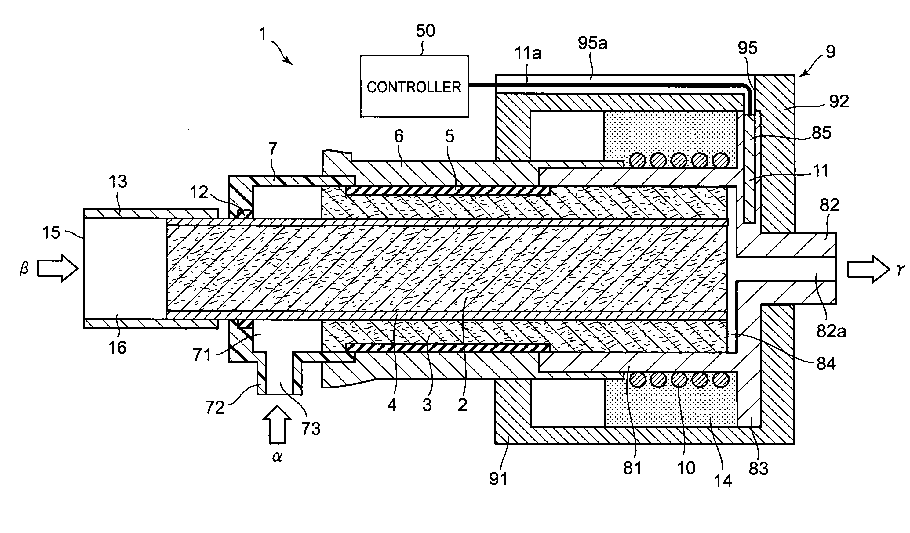
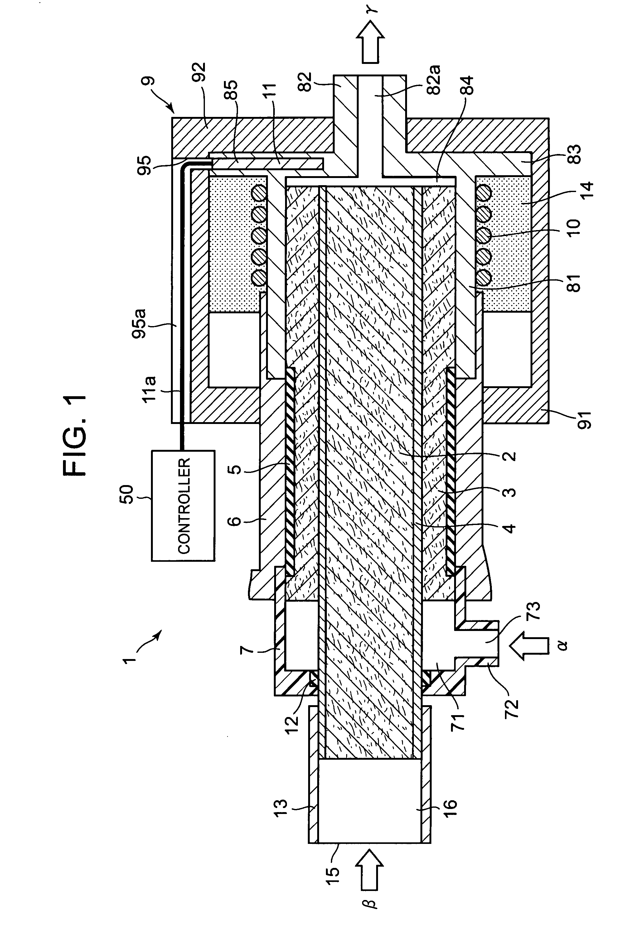
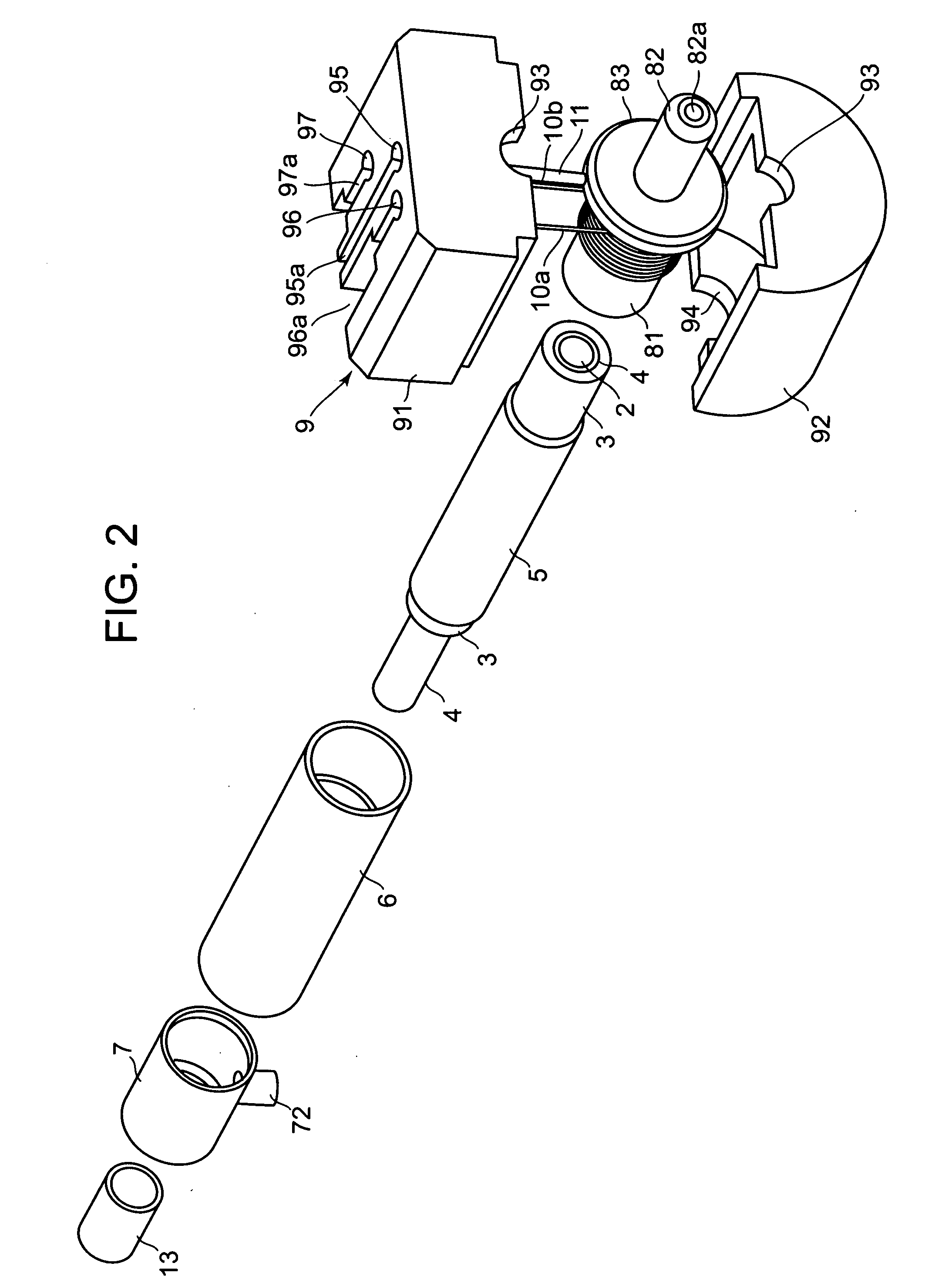
[0054]FIG. 1 is a schematic sectional view of a vaporizer 1. FIG. 2 is an exploded perspective view of an upper surface, a front surface and a right surface of the vaporizer 1.
[0055]As shown in FIGS. 1 and 2, the vaporizer 1 includes a first liquid suction section 3, a second liquid suction section 2, a partition section 4, a contractile tube 5, an elastic tube 6, a first liquid introducing section 7, a second liquid introducing section 13, a discharging section 8, a heat insulation case 9, a heating element 10 and a temperature sensor 11.
[0056]The second liquid suction section 2 is a core material formed into a rod-like shape, more specifically, a columnar shape. The second liquid suction section 2 is a porous body in which a fine space is formed, and the second liquid suction section 2 can suck liquid by capillary action. The second liquid suction section 2 may be formed by solidifying inorganic fiber or organic fiber using bonding material (e.g., epoxy resin), may be formed by si...
second exemplary example
[0103]FIG. 3A is a rear view of a vaporizer 101, FIG. 3B is a sectional view taken along the cut line B-B in FIG. 3A, FIG. 3C is a front view of the vaporizer 101, and FIG. 3D is a sectional view taken along the cut line D-D shown in FIG. 3B.
[0104]As shown in FIGS. 3A to 3D, a body tube 109 is formed into a prismatic tube, a back surface opening and a front surface opening of the body tube 109 are closed, and an internal space is formed in the body tube 109. A partition wall 104 is formed inside of the body tube 109. The partition wall 104 is in parallel to an upper surface and a lower surface of the body tube 109. The internal space of the body tube 109 is partitioned by the partition wall 104 into vertical two spaces extending from front to rear of the body tube 109. The partition wall 104 is connected to a rear end surface, and inner sides of left and right side surfaces of the body tube 109, and is not connected to an inner side of the front end surface of the body tube 109. The...
embodiment 1
[0134]Experiments were conducted. In the experiments, a vaporizer 501 as shown in FIG. 5 was used as a comparative example. In the vaporizer 501, the integral member comprising the partition section 4, the first liquid suction section 3 and the second liquid suction section 2 shown in FIG. 1 is replaced by one cylindrical liquid suction section 502, the elastic tube 6 is elongated, and the first liquid introducing section 7 is removed. Except these points, the vaporizer 501 is the same as the vaporizer 1, a pump is connected to a flow rate meter, the flow rate meter is connected to the elastic tube 6, and the discharge hole 82a of the discharging opening 82 is opened. Conditions of the liquid suction section 502 are as follows:
[0135](a) The liquid suction section 502 (columnar body): a pore ratio is 41%, a particle diameter is 3 μm, a diameter is 1.5 mm, a length is 10.0 mm, and 2 mm of tip end is heated to 130° C. by the heating element 10 through the accommodating section 81, and
[...
PUM
| Property | Measurement | Unit |
|---|---|---|
| Temperature | aaaaa | aaaaa |
| Thickness | aaaaa | aaaaa |
| Boiling point | aaaaa | aaaaa |
Abstract
Description
Claims
Application Information
 - R&D Engineer
- R&D Manager
- IP Professional
- Industry Leading Data Capabilities
- Powerful AI technology
- Patent DNA Extraction
Browse by: Latest US Patents, China's latest patents, Technical Efficacy Thesaurus, Application Domain, Technology Topic, Popular Technical Reports.
© 2024 PatSnap. All rights reserved.Legal|Privacy policy|Modern Slavery Act Transparency Statement|Sitemap|About US| Contact US: help@patsnap.com


