Steel For Mechanical Parts, Method For Producing Mechanical Parts From Said Steel And The Thus Obtainable Mechanical Parts

Inactive Publication Date: 2007-08-23
ASCOMETAL SA
View PDF4 Cites 0 Cited by
  • Summary
  • Abstract
  • Description
  • Claims
  • Application Information

AI Technical Summary

Benefits of technology

[0060] The composition is also adjusted, in particular owing to the combined presence of aluminium, niobium and nitrogen in defined contents, so that the size of the grains remains controlled, even when the carburising or the carbonitriding is carried out at high temperature.
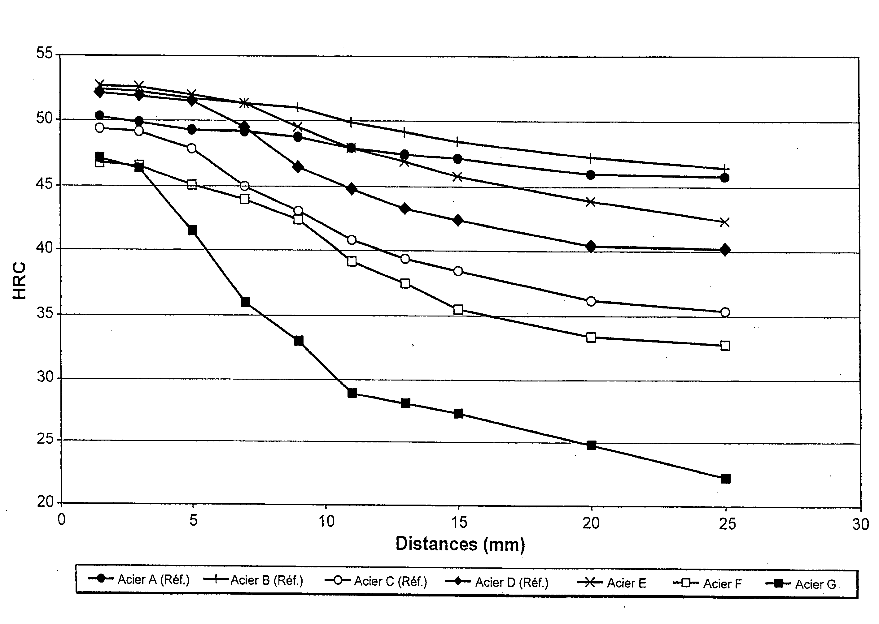
[0061] Finally, the composition of the steel must of course provide the desired mechanical properties for the use of the component. The criteria to be monitored more particularly include the carburised depth (conventionally defined as the depth at which the measured hardness is 550 HV), the deviation of hardness between the surface and the core of the carburised component, which must be as low as possible in order to minimise the deformations during quenching, and the core hardness which must be high so that the component responds effectively to stresses during operation, and therefore has a high level of strength in terms of endurance and fatigue.

Problems solved by technology

However, the application of a high-temperature carburising or cabronitriding operation to the known steels which have been described presents a number of problems.
Firstly, the high temperature may lead to an increase in poorly controlled grains, which is detrimental to the mechanical properties of the component.
Secondly, the carburising or carbonitriding is followed by quenching during which the component is subjected to deformations.
These may require the component to be remachined or, in the most extreme cases, cause it to be rejected.
These problems are accentuated when the quenching is carried out on a component which has just been subjected to a carburising or carbonitriding operation at high temperature and not at a more normal temperature.

Method used


Image

  • Steel For Mechanical Parts, Method For Producing Mechanical Parts From Said Steel And The Thus Obtainable Mechanical Parts
  • Steel For Mechanical Parts, Method For Producing Mechanical Parts From Said Steel And The Thus Obtainable Mechanical Parts

Examples


Embodiment Construction

[0063] The steel according to the invention is intended primarily for producing mechanical components which are subjected to high levels of stress, such as gear elements, and which are intended to be carburised or carbonitrided (preferably at low pressure or in a non-oxidising atmosphere to prevent oxidation of the most oxidisable elements), both at normal temperatures of approximately from 850 to 930° C. and at high temperatures in the order of from 950 to 1050° C. These components must have a high level of fatigue endurance, high strength, and must be only slightly deformed during thermal treatments, such as the quenching operation following the carburising or carbonitriding operation. It has the following composition (all the percentages are percentages by weight).

[0064] The carbon content thereof is between 0.19 and 0.25%. These contents are normal for gear manufacturing steels. Furthermore, this range allows the contents of the other elements to be adjusted, which allows the d...


PUM

PropertyMeasurementUnit
Temperatureaaaaaaaaaa
Fractionaaaaaaaaaa
Fractionaaaaaaaaaa

Abstract

Steel for mechanical components, wherein the composition thereof is, in percentages by weight: 0.19%≦C≦0.25%; 1.1%≦Mn≦1.5%; 0.8%≦Si≦1.2%; 0.01%≦S≦0.09%; trace levels≦P≦0.025%; trace levels≦Ni≦0.25%; 1%≦Cr≦1.4%; 0.10%≦Mo≦0.25%; trace levels≦Cu≦0.30%; 0.010%≦Al≦0.045%; 0.010%≦Nb≦0.045%; 0.0130%≦N≦0.0300%; optionally trace levels≦Bi≦0.10% and / or trace levels≦Pb≦0.12% and / or trace levels≦Te≦0.015% and / or trace levels≦Se≦0.030% and / or trace levels≦Ca≦0.0050%; the balance being iron and impurities resulting from the production operation, the chemical composition being adjusted so that the mean values J3m, J11m, J15m and J25m for five Jominy tests are such that: α=|J11m−J3m×14 / 22−J25m×8 / 22|≦2.5 HRC; and β=J3m−J15m≦9 HRC. Method for producing a mechanical component using this steel and a mechanical component produced in this manner.

Description

TECHNICAL FIELD [0001] The invention relates to the field of steel metallurgy and, more particularly, steels for mechanical components, such as pinions. BACKGROUND TO THE INVENTION [0002] Steels for gear manufacturing must have a high level of resistance to contact fatigue. Most of the time, components produced from these steels are subjected to a carburising or carbonitriding treatment which is intended to provide them with sufficient surface hardness and mechanical strength whilst maintaining a high level of core strength owing, in particular, to a carbon content in the order of from only 0.10 to 0.30%. The carbon content of the carburised layer may be up to approximately 1%. [0003] Various documents describe gear manufacturing steels which are intended to be carburised. These include U.S. Pat. No. 5,518,685, in which the contents of Si and Mn are maintained within relatively low limits (from 0.45 to 1% and from 0.40 to 0.70%, respectively) in order to prevent intergranular oxidat...

Claims


Application Information

Patent Timeline
IPC IPC(8): C23C8/22C23C8/32C22C38/14C22C38/00C22C38/02C22C38/04C22C38/20C22C38/22C22C38/26C22C38/60
CPCC22C38/001C22C38/02C22C38/04C22C38/60C22C38/22C22C38/26C22C38/20
Inventor DAGUIER, PASCALDIERICKX, PIERREPICHARD, CLAUDE
Owner ASCOMETAL SA
Why Eureka
Try Eureka