Uwb short-range radar

Inactive Publication Date: 2007-08-23
ANRITSU CORP
View PDF8 Cites 20 Cited by
  • Summary
  • Abstract
  • Description
  • Claims
  • Application Information

AI Technical Summary

Benefits of technology

[0081] In the UWB short-range radar according to the present invention, a filter or an antenna which suppresses a signal in the RR radiowave emission prohibited band is a

Problems solved by technology

Due to leakage caused by incomplete isolation of the switch circuit 2, outputting of the carrier signal cannot be completely stopped.
In particular, in the UWB having a high frequency, it is difficult to prevent carrier leakage, and pulse-off time is approximately four times pulse-on time in a short-range radar using

Method used


Image

  • Uwb short-range radar
  • Uwb short-range radar
  • Uwb short-range radar

Examples


first embodiment

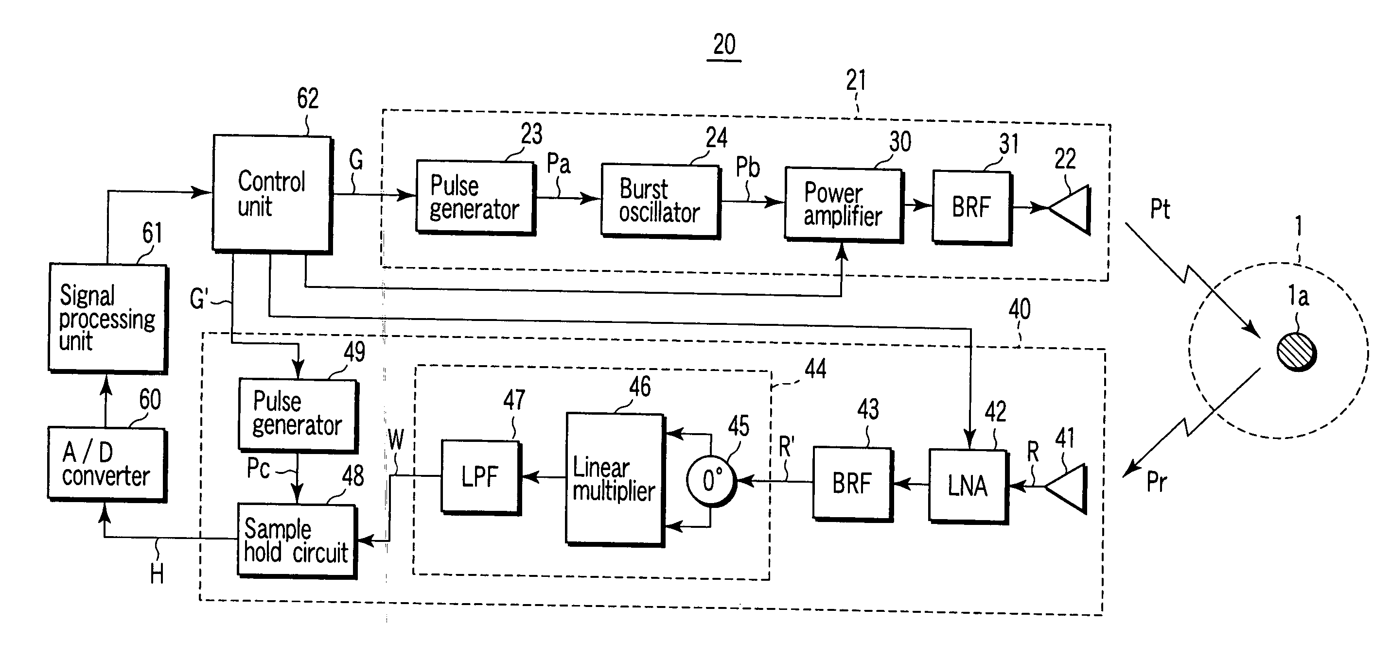
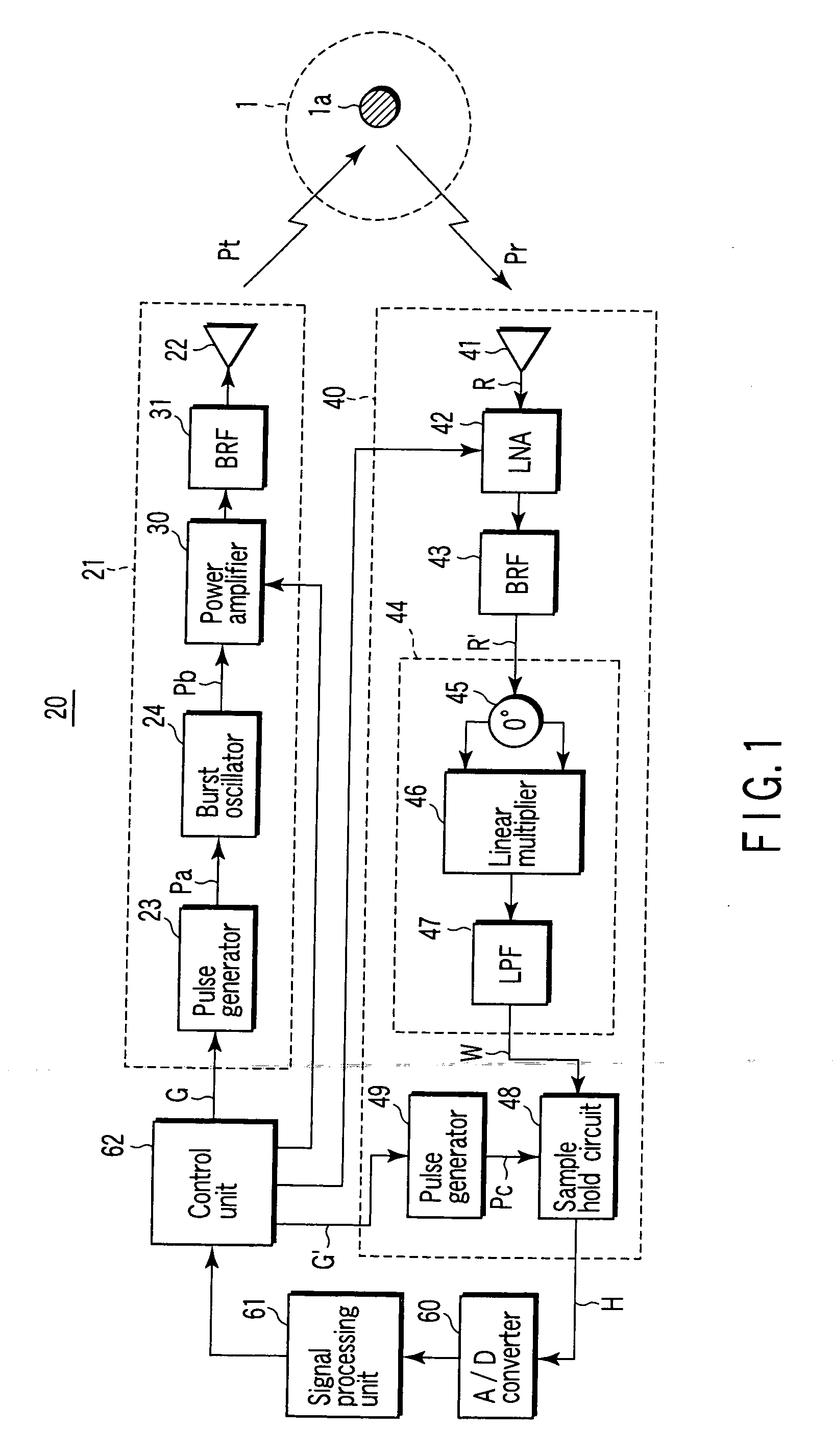
[0109]FIG. 1 is a block diagram shown to explain a configuration of a UWB short-range radar 20 according to a first embodiment to which the present invention is applied.

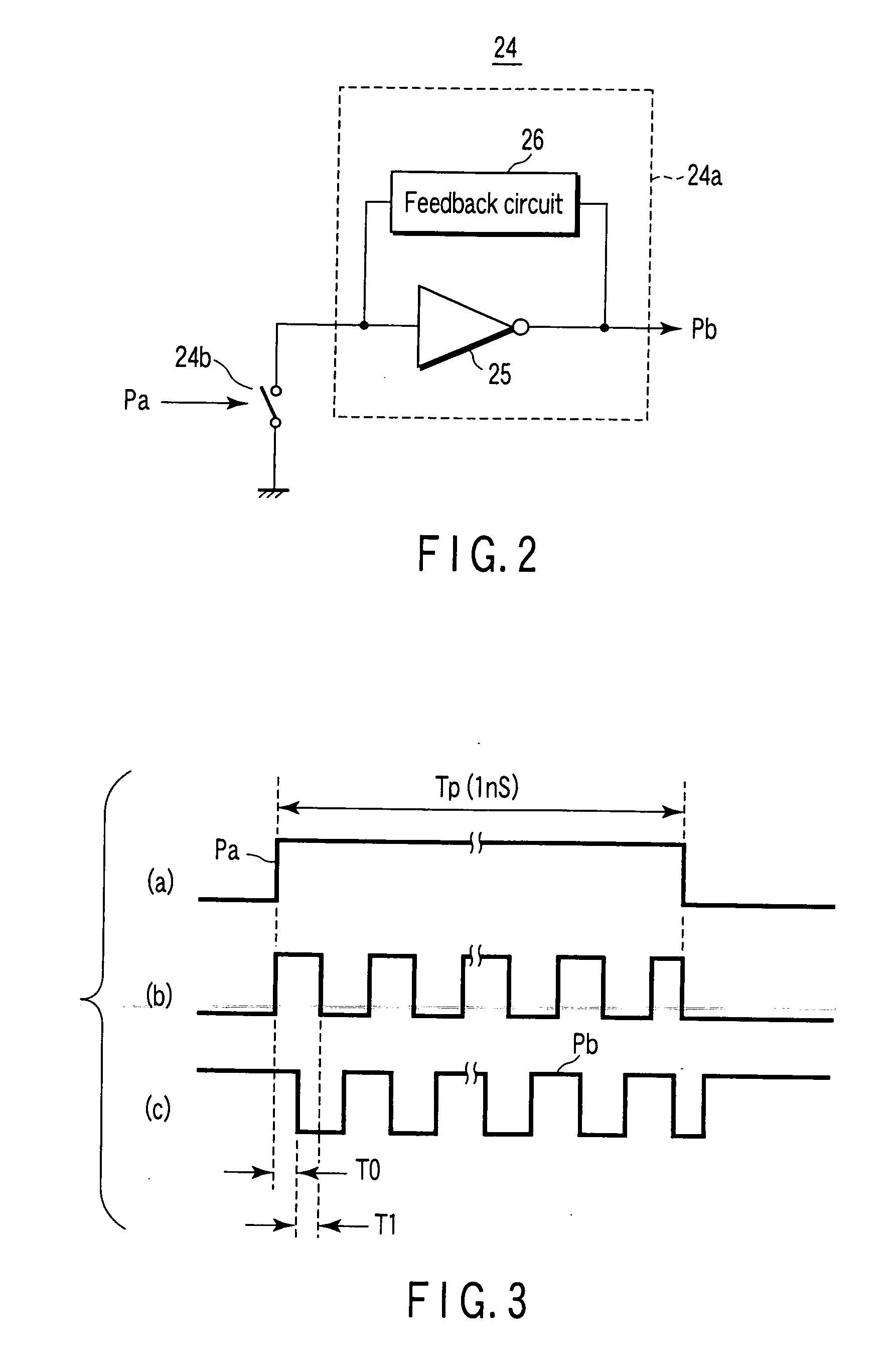
[0110] The UWB short-range radar 20 basically includes: a transmitting unit 21 which emits a short pulse wave Pt which satisfies a predetermined spectrum mask from an antenna 22 into a space 1; a receiving unit 40 which receives a reflected wave Pr obtained by an object 1a existing in the space 1 of the short pulse wave Pt emitted by the transmitting unit 21; and a signal processing unit 61 which performs an analyzing process for the object based on a received signal from the receiving unit 40. The transmitting unit 21 has a pulse generator 23 which outputs pulse signals each having a predetermined width at a predetermined frequency, and a burst oscillator 24 which receives the pulse signal output from the pulse generator 23 and performs an oscillation operation for time corresponding to the width of the pulse signa...


PUM


Abstract

A transmitting unit emits a short pulse wave which satisfies a predetermined spectrum mask from an antenna into space. A receiving unit receives a reflected wave produced by an object existing in space of the short pulse wave emitted by the transmitting unit. A signal processing unit analyzes the object based on an output signal from the receiving unit. The transmitting unit has a pulse generator which outputs pulse signals each having a predetermined width at a predetermined frequency, and a burst oscillator which receives the pulse signal output from the pulse generator and performs an oscillation operation for time corresponding to the width of the pulse signal to output the short pulse signal. A width and a cycle of the pulse signal and an oscillation frequency of the burst oscillator are set such that almost an entire main lobe of a spectrum of the short pulse wave falls within a range of 24.0 to 29.0 GHz in the predetermined spectrum mask, and that a radiation power density to an RR radiowave emission prohibited band held by the predetermined spectrum mask is lower than a peak radiation power density of the main lobe by not less than 20 dB.

Description

TECHNICAL FIELD [0001] The present invention relates to UWB short-range radars, and more particularly, to UWB short-range radars employing a technique to make it possible to cause a short-range radar used in an ultra-wideband (UWB) of 22 to 29 GHz to conform to the rules of International Radio Communication Regulations (RR). BACKGROUND ART [0002] A short-range radar using a UWB is tried to be practically used as an automotive short-range radar or a radar for people with visual impairment. [0003] A short-range radar using a UWB, like a normal radar, emits a short pulse wave from an antenna of a transmitting unit into space and receives a reflected wave from an object existing in space to perform an analyzing process for the object. [0004]FIG. 24 shows a schematic configuration of a transmitting unit of a short-range radar of this type. [0005] More specifically, the transmitting unit receives a carrier signal S of a predetermined frequency in a UWB output from a carrier signal generat...

Claims


Application Information

Patent Timeline
IPC IPC(8): G01S13/62
CPCG01S7/03G01S13/0209H03B5/1215H04B1/7174H03B5/1231H01Q9/27
Inventor TESHIROGI, TASUKUSAITO, SUMIOUCHINO, MASAHARUEJIMA, MASANORI
Owner ANRITSU CORP
Why Eureka
Try Eureka