Dc/dc converter

a converter and dc technology, applied in the direction of pulse technique, process and machine control, instruments, etc., can solve the problems of requiring a new drive system or a new member

Active Publication Date: 2007-08-23
RENESAS ELECTRONICS CORP
View PDF4 Cites 67 Cited by
  • Summary
  • Abstract
  • Description
  • Claims
  • Application Information

AI Technical Summary

Benefits of technology

[0016]In view of these circumstances, the present invention has been made for solving the above problems and an object thereof is to provide a circuit system and a mounting system where a self turn-on phenomenon can be prevented in a non-isolated DC / DC converter, particularly, a system-in-package for a DC / DC converter without newly adding a member or changing a drive system.

Problems solved by technology

However, since the technique described in Patent Document 2 or Patent Document 3 requires a circuit for generating a negative potential or an auxiliary switch additionally to prevent self turn-on phenomenon, such a problem arises that an additional member or change of a drive system is required.

Method used


Image

  • Dc/dc converter
  • Dc/dc converter
  • Dc/dc converter

Examples


first embodiment

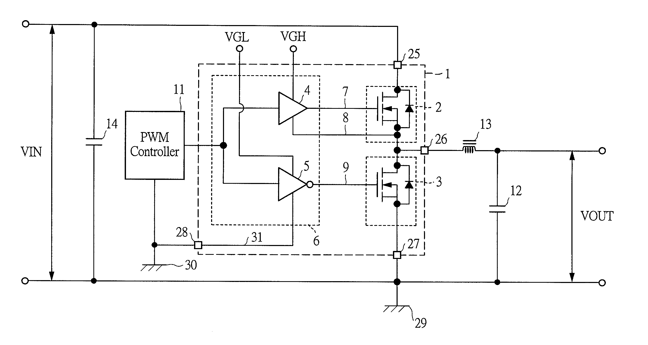
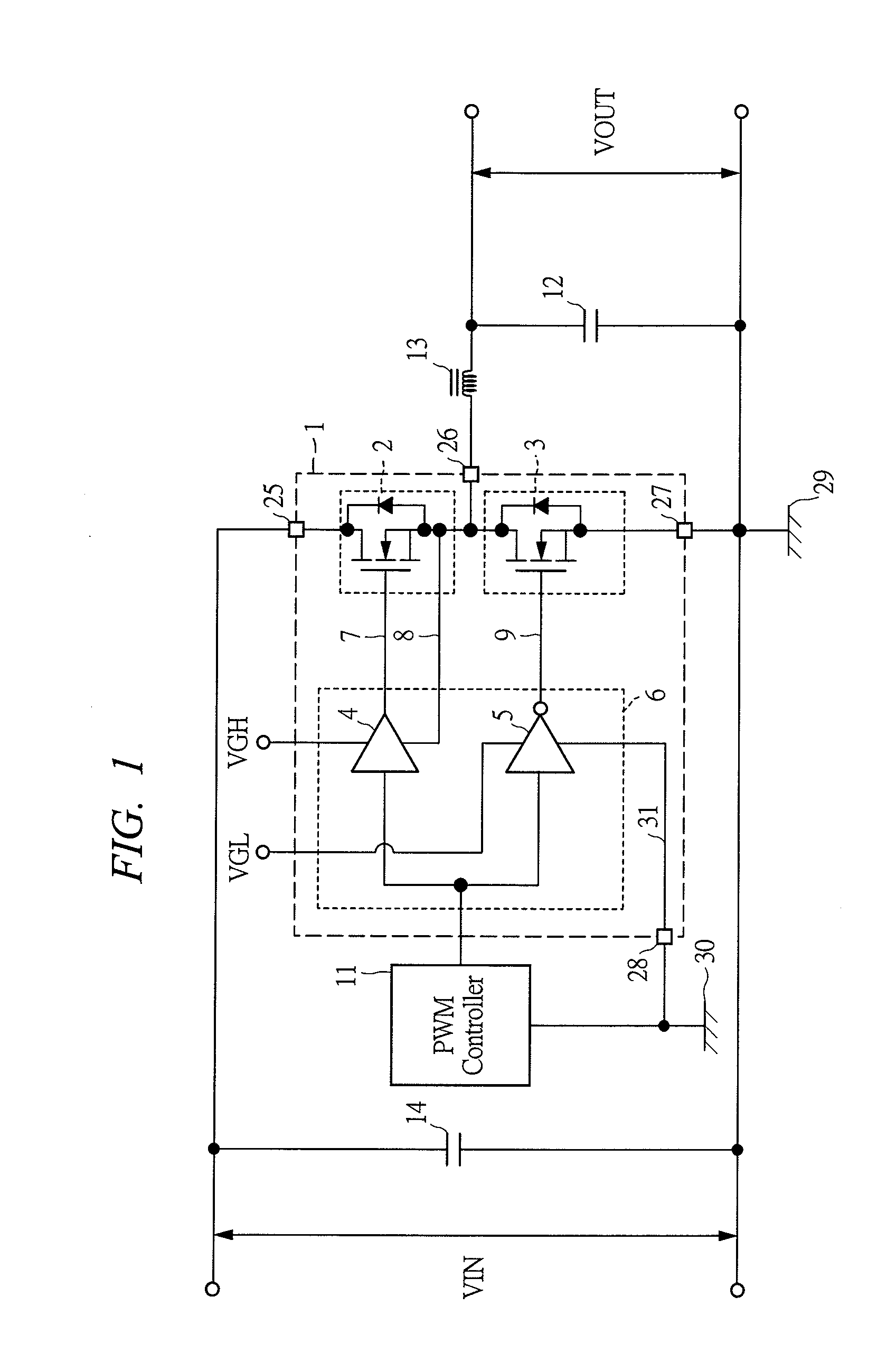
[0040]FIG. 1 is a circuit diagram showing a DC / DC converter using a system-in-package according to a first embodiment of the present invention. In a DC / DC converter according to the present embodiment, a system-in-package 1 comprises a high-side MOSFET (a high-side switch) 2, a low-side MOSFET (a low-side switch) 3, a high-side pre-driver 4 for driving a gate of the high-side MOSFET 2, and a low pre-driver 5 for driving a gate of the low-side MOSFET 3, where the pre-drivers 4 and 5 are formed as a driver IC 6 in one chip, and three chips of the high-side MOSFET 2, the low-side MOSFET 3, and the driver IC 6 are mounted in one package.

[0041]Since an operation principle and respective constituent elements of a DC / DC converter using the system-in-package 1 are similar to those of the conventional DC / DC converter shown in FIG. 10 described above, detailed description thereof is omitted here.

[0042]A feature of the DC / DC converter of the present embodiment lies in that a reference potentia...

second embodiment

[0049]FIG. 6 is a circuit diagram showing a DC / DC converter using a discrete device according to a second embodiment of the present invention. A feature of the second embodiment lies in that a reference voltage for a pre-driver 5 is taken from a portion nearest to a ground terminal of an input capacitor 14 through a wire 35. The second embodiment is a technique suitable for a DC / DC converter using the conventional discrete device instead of the system-in-package.

[0050]FIG. 7 is a diagram showing one example of a wiring pattern of a print circuit board using the discrete device according to the second embodiment, where the reference voltage for the pre-driver 5 is taken from a portion nearest to the ground terminal of the input capacitor 14 through the wire 35 in the wiring pattern on the print circuit board. Conventionally, as shown in FIG. 15, the reference potential is taken from a portion near to the source of the low-side MOSFET 3 through the wire 10.

[0051]In FIG. 7 and FIG. 15,...

third embodiment

[0053]FIG. 8 is a circuit diagram of a DC / DC converter in which an auxiliary Schottky barrier diode is built-in according to a third embodiment. A feature of the third embodiment lies in that a Schottky barrier diode (SBC) 36 is built-in between a gate and a source of a low-side MOSFET 3. In the present invention, since a gate voltage is changed to a negative potential only for a moment when self turn-on occurs and an output voltage of a pre-driver 5 is changed to a negative potential at this time, there is a possibility that a pn junction in a driver IC 6 operates so that the pre-driver 5 causes malfunction or breaking.

[0054]A feature of the third embodiment lies in that the gate voltage is clamped at −Vf which is a forward voltage of the auxiliary SBD 36 by incorporating the auxiliary SBD 36 between the gate and the source of the low-side MOSFET in order to prevent the above-described malfunction. Since the forward voltage of SBD is generally low relative to a forward voltage at t...


PUM


Abstract

In a non-isolated DC/DC converter, a reference potential for a low-side pre-driver which drives a gate of a low-side MOSFET is applied from a portion except for a main circuit passing through a high-side MOSFET and the low-side MOSFET so that a parasitic inductance between a source of the low-side MOSFET and the pre-driver is increased without increasing the sum of parasitic inductances in the main circuit and negative potential driving of the gate of the low-side MOSFET can be performed and a self turn-on phenomenon can be prevented without adding any member and changing drive system.

Description

CROSS-REFERENCE TO RELATED APPLICATION[0001]The present application claims priority from Japanese Patent Application No. JP 2006-046171 filed on Feb. 23, 2006, the content of which is hereby incorporated by reference into this application.TECHNICAL FIELD OF THE INVENTION[0002]The present invention relates to a technique for a non-isolated DC / DC converter, and in particular to a technique effectively applied to a circuit system and a mounting system which can prevent a self turn-on phenomenon without adding any new member or changing a driving system.BACKGROUND OF THE INVENTION[0003]For example, a non-isolated DC / DC converter used in power source circuit for a desktop PC, a notebook PC, a game machine, or the like is in a trend of large current use and high frequency use according to demand for large current use in a CPU (Central Processing Unit) or an MPU (Micro Processing Unit) or demand for size reduction of a choke coil or an input / output capacitor which is a passive part. The DC...

Claims


Application Information

Patent Timeline
Patent Type & Authority Applications(United States)
IPC IPC(8): H02M3/335
CPCH01L24/49H01L2224/48137H01L2924/12032H01L2924/30107H01L2924/13091H01L2924/01033H01L2924/01006H01L2924/01005H03K17/6871H03K17/165H03K17/0822H02M1/08H01L2924/01082H01L2224/48247H01L2224/49175H01L2924/01013H01L2924/00H01L24/48H01L2924/00014H01L2924/12036H01L2924/14H03K17/166H01L2224/45099
Inventor SHIRAISHI, MASAKIHASHIMOTO, TAKAYUKIAKIYAMA, NOBORU
Owner RENESAS ELECTRONICS CORP
Why Eureka
Try Eureka