Magnetic memory

a magnetic memory and memory technology, applied in the field of magnetic memory, can solve the problems of accidental magnetization reversal, heat generation in tmr element portions, breakdown due to voltage application, etc., and achieve the effect of reducing the shape anisotropy in the magnetization direction, shortening the circuit, and reducing the anisotropy of the writing curren

Active Publication Date: 2007-08-23
TDK CORPARATION
View PDF2 Cites 31 Cited by
  • Summary
  • Abstract
  • Description
  • Claims
  • Application Information

AI Technical Summary

Benefits of technology

[0024]It is necessary that the first wiring and the second wiring are electrically separated since these are different in functions. Since the first wiring and the second wiring are interposed with the step and the margin region exists therebetween, there is an advantage that the first wiring and the second wiring are not easily short-circuited.
[0025]Moreover, each storage area further includes a second spin filter interposed between the magnetoresistance effect element and the common wiring. In this case, since two spin filters are interposed between the first wiring and the common wiring, filtering performance of spinning electrons to be injected into the magnetoresistance effect element can be improved, and thus the writing current can further be lowered.
[0026]Moreover, an area S2 of the second region is equal to or less than 50% of an area S1 of the first region. When the area S2 of the second region on which the second wiring is provided is large, the area of the spin filter layer is limited, and the area of a ferromagnetic layer PN1 is reduced, so that shape anisotropy in the magnetization direction decreases to impair stability in the magnetization direction. In addition, a spin polarized current that flows to the magnetoresistance effect element results in an uneven density distribution. For the above reasons, magnetization reversal efficiency is degraded, and the magnetization reversal threshold value increases, so that the area S2 is preferably small. However, if the area S2 is too small, the reading current is limited.
[0027]According to the magnetic memory of the present invention, even when the magnetosensitive layer that can be magnetization-reversed is reduced in area so as to reduce the writing current, it is not necessary to considerably lower the reading current, and thus recording density can be improved.

Problems solved by technology

That is, the TMR element has a relatively high resistance, and when a writing current is supplied thereto, there is a problem such that heat generation in a TMR element portion increases, and a breakdown due to voltage application occurs in some cases.
However, when the current necessary for writing is reduced, there is a possibility that a magnetization reversal occurs accidentally due to a current supplied when reading out information.
However, in this case, there is a concern that the function to read out information itself can be impaired, and thus it becomes difficult to increase the memory in density.

Method used


Image

  • Magnetic memory
  • Magnetic memory
  • Magnetic memory

Examples


Embodiment Construction

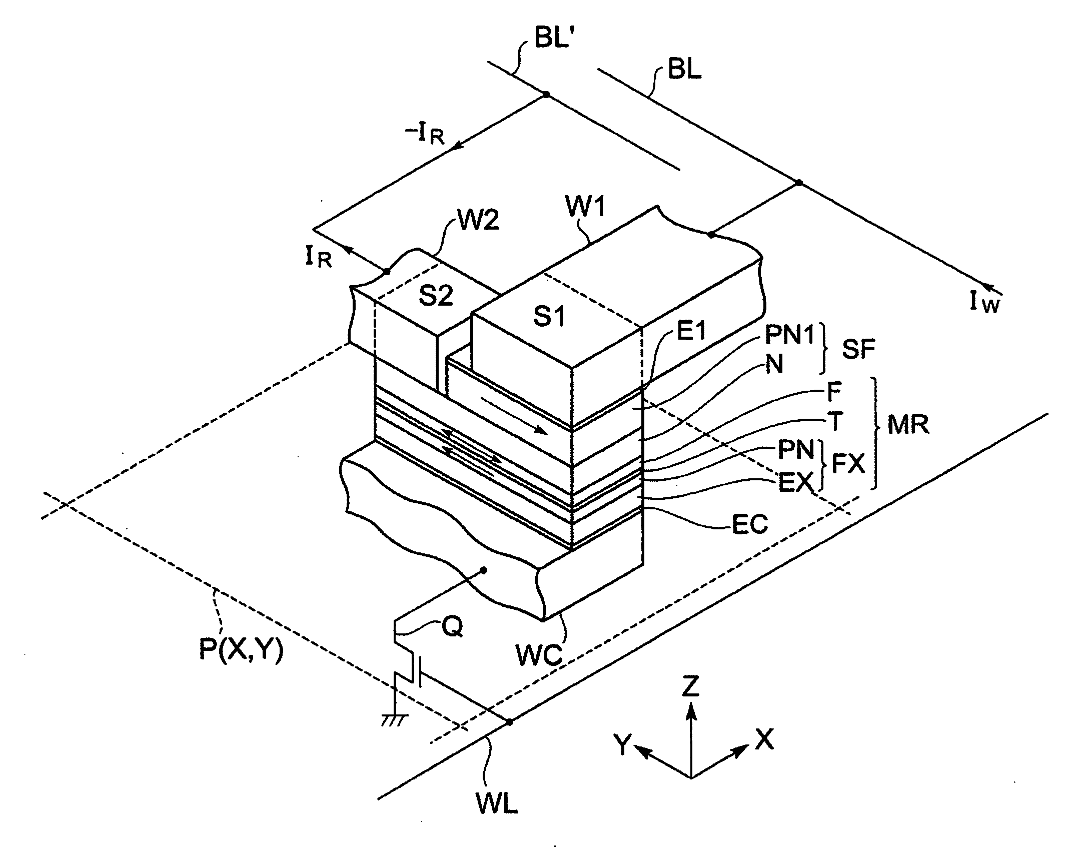
[0052]Hereinafter, a magnetic memory according to an embodiment will be described. Here, identical elements are designated with identical numerical symbols so as to avoid overlapping descriptions. The magnetic memory according to the embodiment is formed by arranging X-rows and Y-columns of a plurality of storage areas P (X, Y), and each storage area P (X, Y) includes a magnetoresistance effect element MR.

[0053]FIG. 1 is a perspective view of one storage area P (X, Y).

[0054]Each storage area P (X, Y) includes first wiring W1 for supplying a writing current IW, second wiring W2 for supplying a reading current IR, common wiring WC, a magnetoresistance effect element MR, and a spin filter SF provided on the magnetoresistance effect element MR.

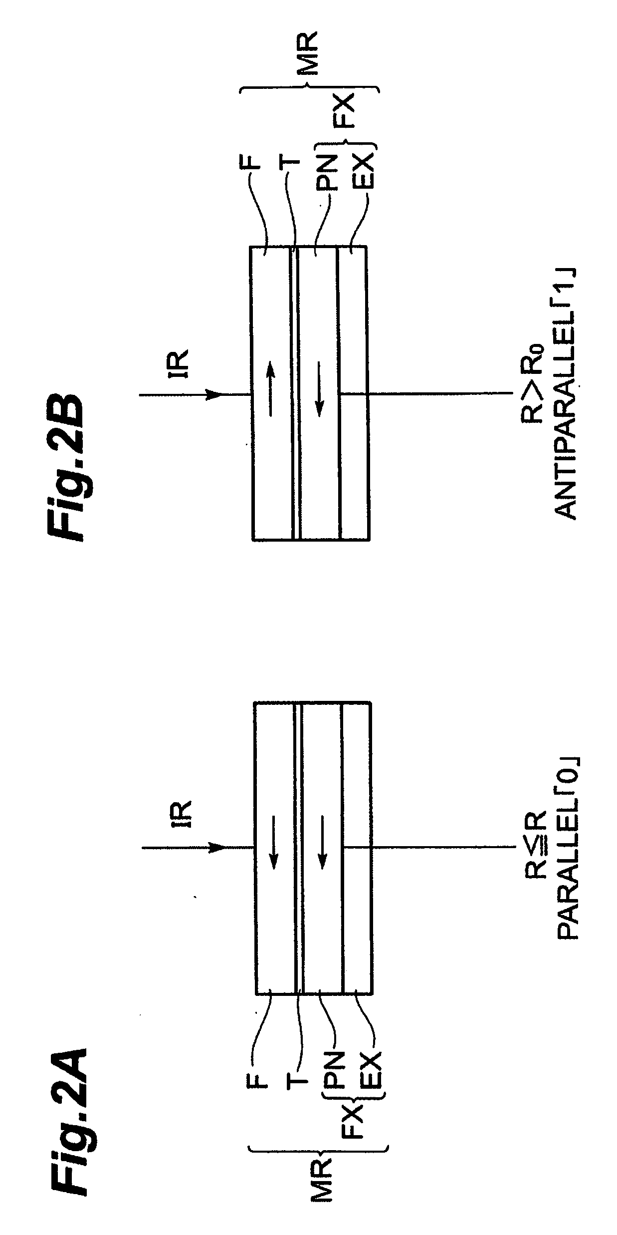
[0055]The magnetoresistance effect element MR is a TMR element including an insulating layer T between magnetosensitive layer F and a pinned layer FX. The TMR element is an element using a phenomenon that the ratio of electrons passing through the...


PUM


Abstract

A magnetoresistance effect element is also located between second wiring and common wiring. The magnetoresistance effect element is electrically connected to the second wiring without a spin filter. When a reading current is supplied between the second wiring for supplying a reading current and the common wiring, since this is not supplied via a spin filter, no spin polarized current is supplied into the magnetoresistance effect element, so that it becomes difficult to magnetization-reverse a magnetosensitive layer. Even in a structure where, in order to improve recording density, the magnetosensitive layer is reduced in area so as to lower a writing current, no magnetization reversal occurs due to a supply of the reading current, and information can be read out without making the reading current considerably small in comparison with the writing current.

Description

BACKGROUND OF THE INVENTION[0001]1. Field of the Invention[0002]The present invention relates to a magnetic memory.[0003]2. Related Background Art[0004]An MRAM (Magnetic Random Access Memory) has a structure where TMR (Tunnel Magnetoresistance) elements are disposed at junctions between bit lines and word lines wired in a lattice form. A normal TMR element has a ferromagnetic layer / nonmagnetic insulating layer / ferromagnetic layer, three-layer structure having a nonmagnetic layer between two ferromagnetic layers. The ferromagnetic layers are normally made of a magnetic transition metal element (Fe, Co, Ni) or an alloy of magnetic transition metal elements (CoFe, CoFeNi, NiFe, or the like), and the nonmagnetic insulating layer is made of Al2O3, MgO, or the like.[0005]One of the ferromagnetic layers (pinned layer) forming the TMR element is fixed in the direction of magnetization, while the other ferromagnetic layer (magnetosensitive layer or free layer) is turned in the direction of m...

Claims


Application Information

Patent Timeline
Patent Type & Authority Applications(United States)
IPC IPC(8): G11C11/14
CPCG11C11/16
Inventor KOGA, KEIJI
Owner TDK CORPARATION
Why Eureka
Try Eureka