Frequency ratio digitizing temperature sensor with linearity correction

a temperature sensor and frequency ratio technology, applied in heat measurement, instruments, pulse techniques, etc., can solve the problems of nonlinearity distortion of linearity of digital output signals, additional drifts and nonlinearity of oscillator frequency

Active Publication Date: 2007-08-23
NAT SEMICON CORP
View PDF23 Cites 33 Cited by
  • Summary
  • Abstract
  • Description
  • Claims
  • Application Information

AI Technical Summary

Problems solved by technology

In conventional frequency ratio digitizing temperature sensors, non-ideal characteristics of the various elements of the sensor circuit result in non-linearity of the digital output signals.
Propagation delays through the oscillators result in distortion of the linearity of the frequency of the digital output signal.
The temperature coefficients of the resistors and capacitors forming each oscillator may cause additional drifts and nonlinearity in the oscillator frequency as temperature changes.
Some prior art solutions to correcting or minimizing the linearity errors force the corrected system to be less useful in common applications.
This results in a conversion time which increases significantly as the temperature increases, which can be inconvenient when the desired application is an output stream of samples taken at fixed, constant intervals.
However, the crystal oscillator is an external component and the use of a crystal oscillator increases the cost as well as the circuit area required for implementing the frequency ratio ADC.
It does not apply to frequency ratio ADCs in part because frequency ratio ADCs use four distinct input ports and linearity correction for signal input and reference port is not directly applicable

Method used


Image

  • Frequency ratio digitizing temperature sensor with linearity correction
  • Frequency ratio digitizing temperature sensor with linearity correction
  • Frequency ratio digitizing temperature sensor with linearity correction

Examples


second embodiment

[0078] The derivation of the parameters Kp, Kv and Nc is better described by use of an input generation circuit with normalized current values. FIG. 6 is a schematic diagram of an input generation circuit for the frequency ratio digitizing temperature sensor of FIG. 1 according to the present invention. Referring to FIG. 6, input generation circuit 200 is constructed in the same manner as input generation circuit 100 of FIG. 4 except for the current multiplication factors applied in the linearity IDAC circuits. In FIG. 6, the first and second corrected currents are normalized to maintain a constant total current magnitude for each current throughout the temperature sensor. That is, in input generation circuit 100, when the fraction Kp*IPTAT current is added to the current Inpo, the resulting corrected reference current In—1 will necessarily have an increased current magnitude. The same applies to the corrected reference current Ivr. In some applications, the increased current magnit...

third embodiment

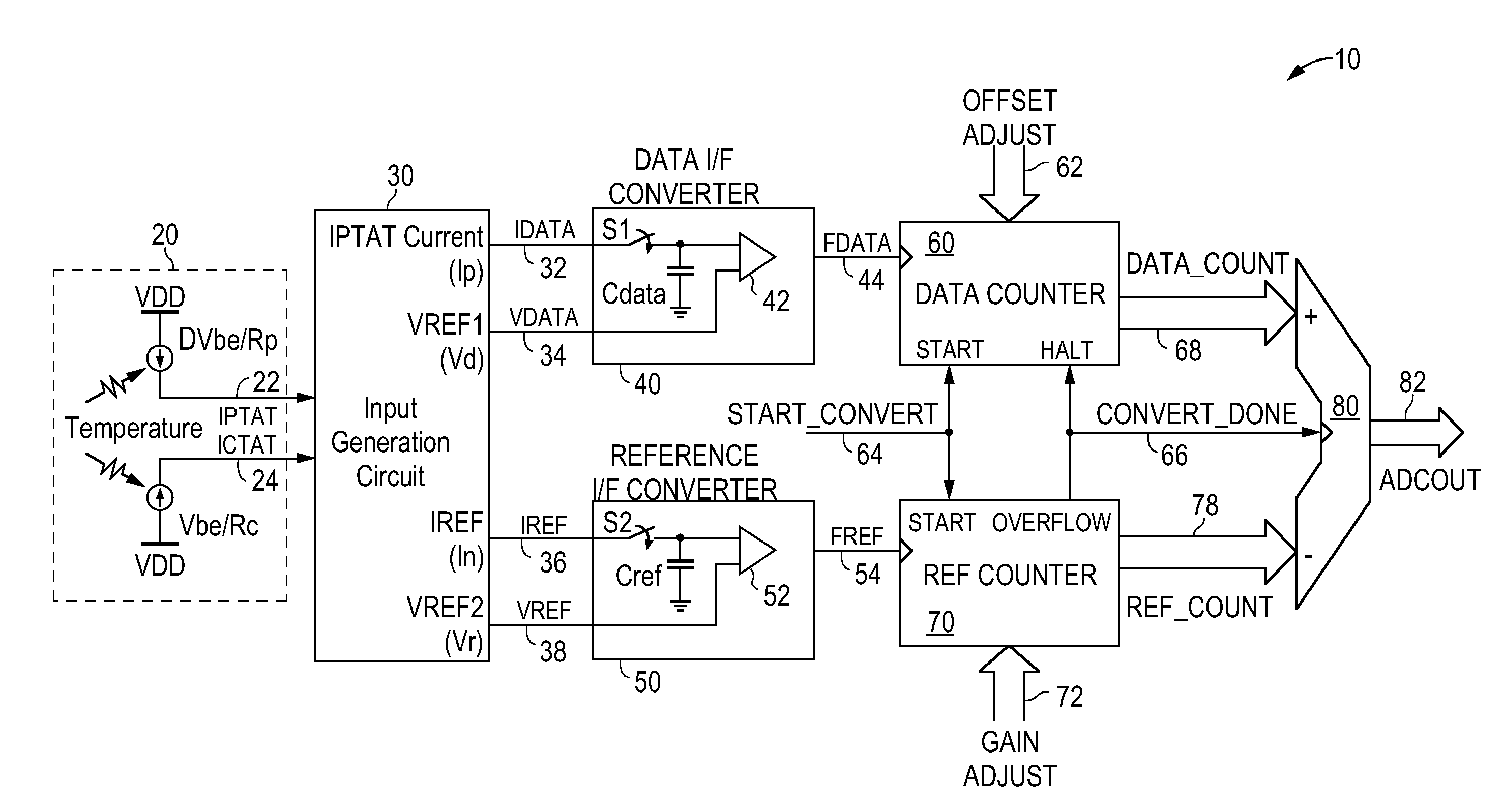
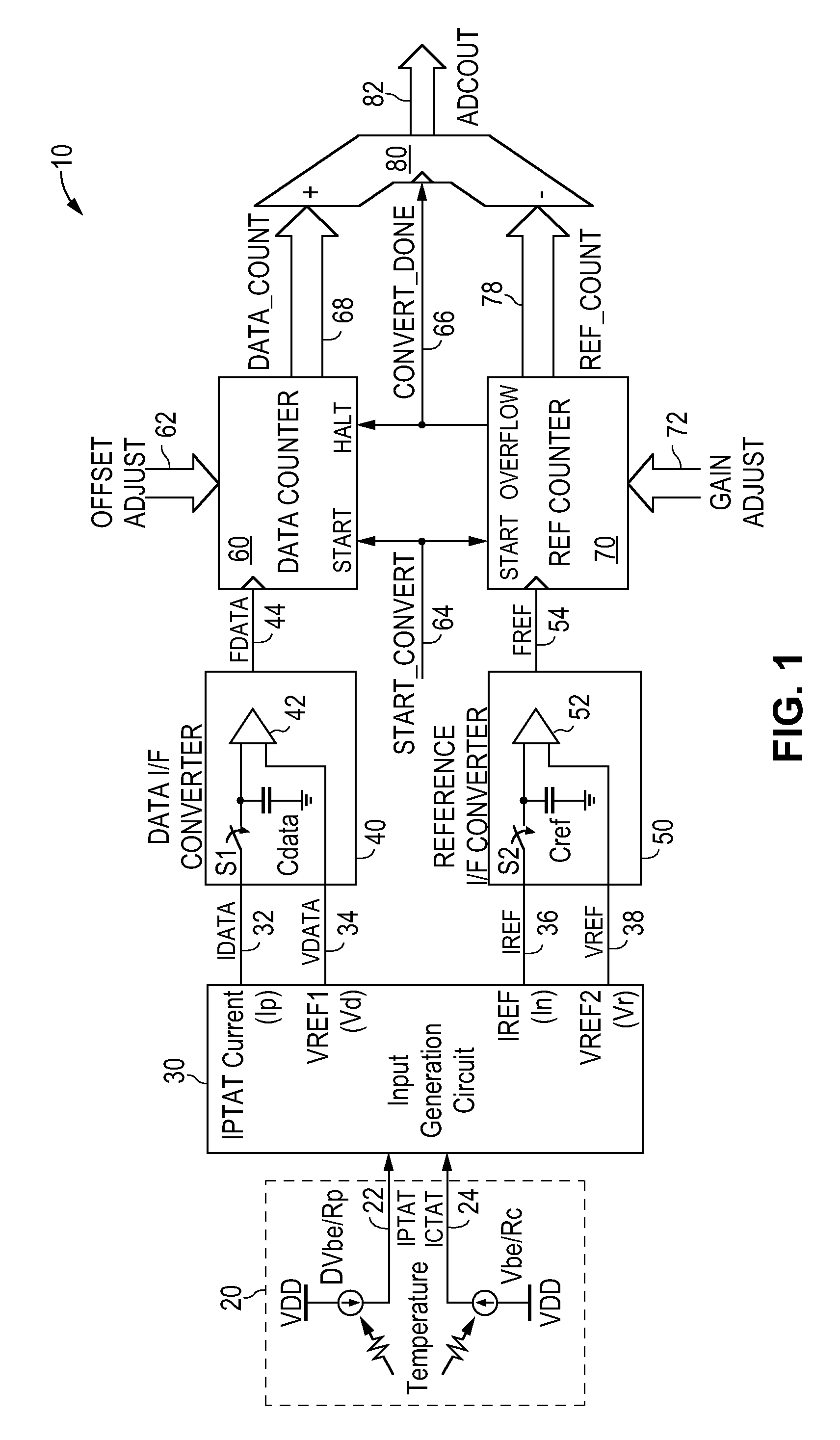
[0104]FIG. 12 is a schematic diagram of an input generation circuit implementing 2-port linearity correction for the frequency ratio digitizing temperature sensor of FIG. 1 according to the present invention. Referring to FIG. 12, input generation circuit 300 is constructed in the same manner as input generation circuit 100 of FIG. 4 except for the omission of the reference linearity IDAC. Thus, in the 2-port linearity correction method, the corrected reference current In—1 (node 318) generated by summing the current Inpo (node 308) and a Kp fraction of the PTAT current IPTAT1345 is used simultaneously to modify the reference current Iref of the reference oscillator and the reference voltage Vdata of the data oscillator. Specifically, the corrected reference current In—1 is mirrored by a buffer 319 to form current In which is used as the input reference current Iref (node 336) for the reference oscillator. The corrected reference current In—1 is applied to a resistor Rdata to genera...


PUM

PropertyMeasurementUnit
temperatureaaaaaaaaaa

Abstract

A frequency ratio digitizing temperature sensor for generating a linearity-corrected temperature output signal includes an input generation circuit receiving a PTAT current and a CTAT current and a frequency ratio ADC including data and reference oscillators. The input generation circuit generates a first current from the weighted sum of the PTAT current and the CTAT current and also generates a first corrected current being the sum of the first current and a first portion of the PTAT current. The input generation circuit provides a first output current indicative of the PTAT current and a first output voltage generated by applying the first corrected current to a first resistor for use with the data oscillator and provides a second output current being the first corrected current and a second output voltage generated by applying the first current to a second resistor for use with the reference oscillator of the ADC.

Description

FIELD OF THE INVENTION [0001] The invention relates to digitizing temperature sensors and, in particular, to the linearization of the digital temperature measurements of a frequency ratio digitizing temperature sensor. DESCRIPTION OF THE RELATED ART [0002] Frequency ratio digitizing temperature sensors operating to measure temperature by changing the frequency of an oscillator are well known. More generally, such a temperature sensor is implemented using a frequency ratio analog-to-digital converter (ADC) to measure an input signal that varies with temperature. In general, a frequency ratio digitizing temperature sensor includes two oscillators—a reference oscillator and a data oscillator. The reference oscillator defines the conversion interval where a fixed number of clock periods of the reference frequency is used to indicate the conversion period. The frequency of the data oscillator, the data frequency, is varied with temperature and the ratio of the data frequency to the refer...

Claims


Application Information

Patent Timeline
Patent Type & Authority Applications(United States)
IPC IPC(8): G01K11/22
CPCG01K7/01
Inventor BLOM, ERIC D.WAN, JUNURIE, STUART H.
Owner NAT SEMICON CORP
Why Eureka
Try Eureka