Method and apparatus for visual neural stimulation

a neural stimulation and visual technology, applied in electrotherapy, therapy, etc., can solve the problems of increasing density and charge density, large prosthetic devices, and insufficient simulated vision to truly assist the visually impaired, and achieves high temporal and spatial precision, increase the spatial resolution of artificial sigh

Inactive Publication Date: 2007-08-23
SALK INST FOR BIOLOGICAL STUDIES +1
View PDF31 Cites 51 Cited by
  • Summary
  • Abstract
  • Description
  • Claims
  • Application Information

AI Technical Summary

Problems solved by technology

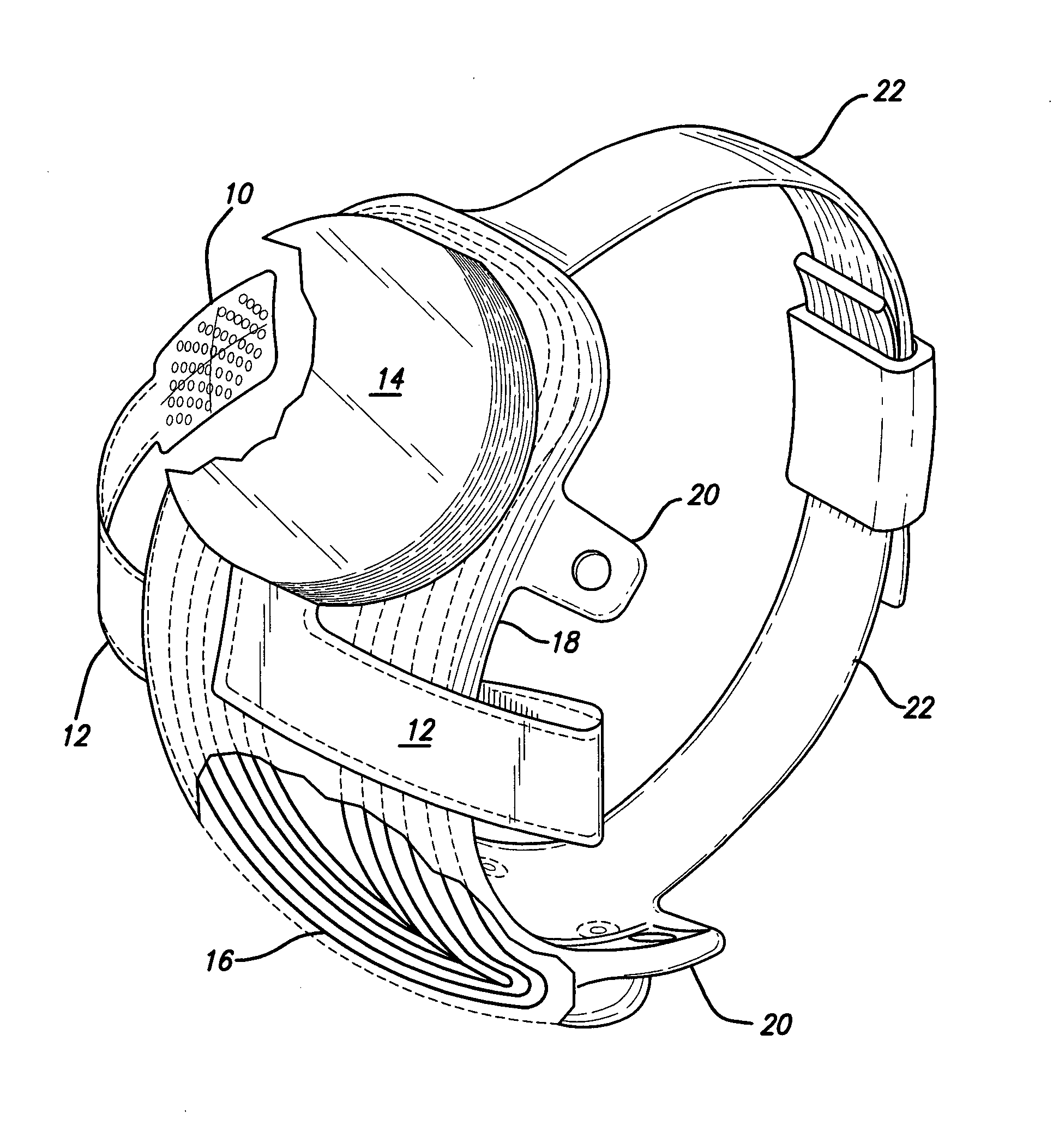
While some of these early attempts met with some limited success, these early prosthetic devices were large, bulky and could not produce adequate simulated vision to truly aid the visually impaired.
When the electrode surface area is reduced, current density and charge density increase rapidly, and high charge densities are known to cause tissue damage by electrochemical reactions (Pollen 1977; Brummer et al.
A comprehensive literature review reveals that the feasibility of stimulation with arrays of small electrodes in mammalian tissue has not been adequately tested.
Stimulation, furthermore, is always limited to a single stimulation site, precluding the study of stimulation using multiple electrodes and their interaction effects.

Method used


Image

  • Method and apparatus for visual neural stimulation
  • Method and apparatus for visual neural stimulation
  • Method and apparatus for visual neural stimulation

Examples


Embodiment Construction

[0036] The following description is of the best mode presently contemplated for carrying out the invention. This description is not to be taken in a limiting sense, but is made merely for the purpose of describing the general principles of the invention. The scope of the invention should be determined with reference to the claims.

[0037] Recent attempts to restore vision in the blind have met with extraordinary success. Electrical stimulation of retinas in people with neurodegenerative diseases has demonstrated the potential for direct excitation of neurons as a means of re-establishing sight. Long-term retinal implants in several profoundly blind people were shown to produce perceptions of light and allowed for the detection of motion and discrimination of very simple shapes (Humayun 2003; Humayun et al. 2003). Such achievement brings hope to the millions of people worldwide who suffer from photoreceptor loss due to advanced retinitis pigmentosa or age-related macular degeneration ...


PUM

PropertyMeasurementUnit
sizeaaaaaaaaaa
sizeaaaaaaaaaa
currentaaaaaaaaaa

Abstract

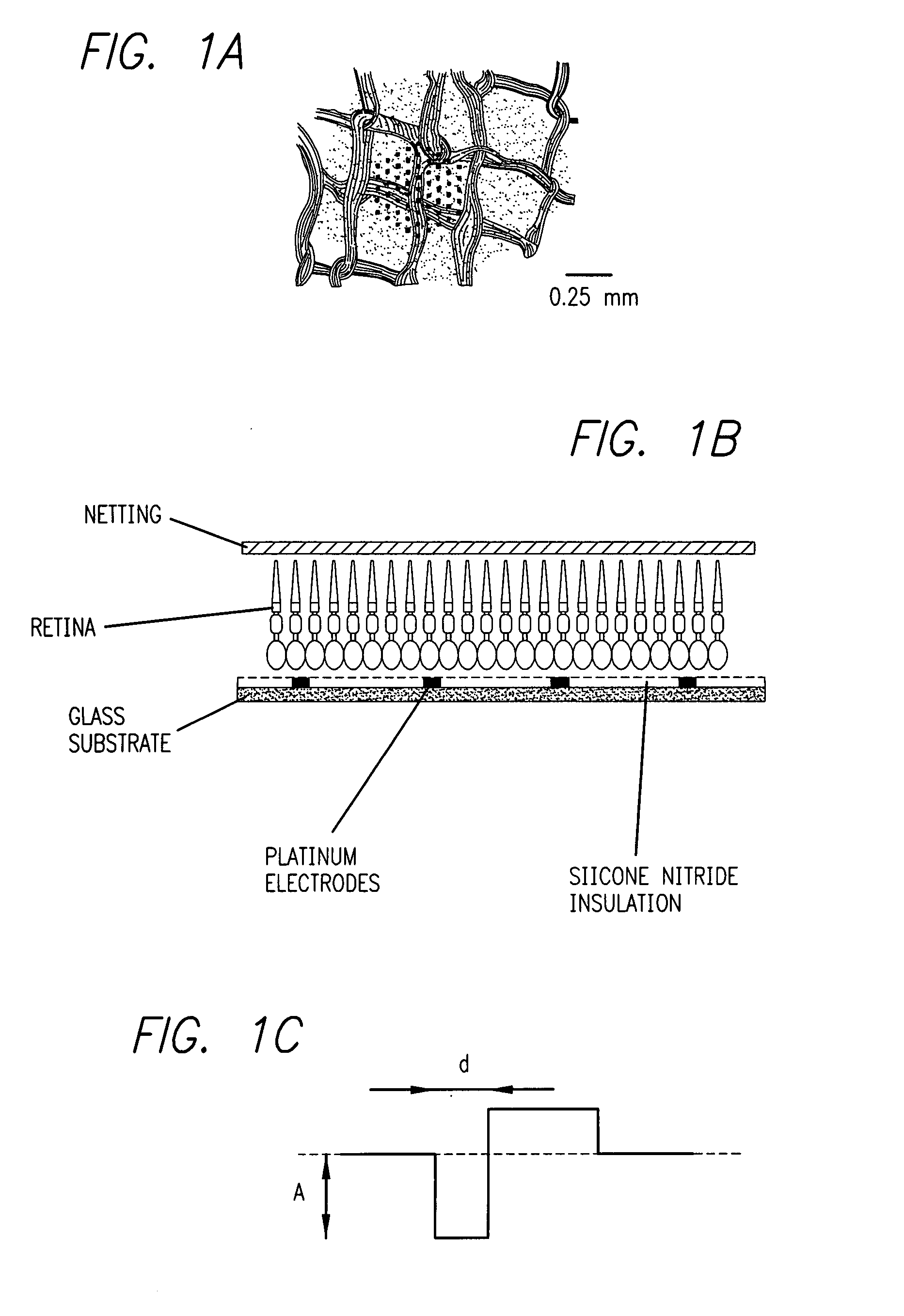
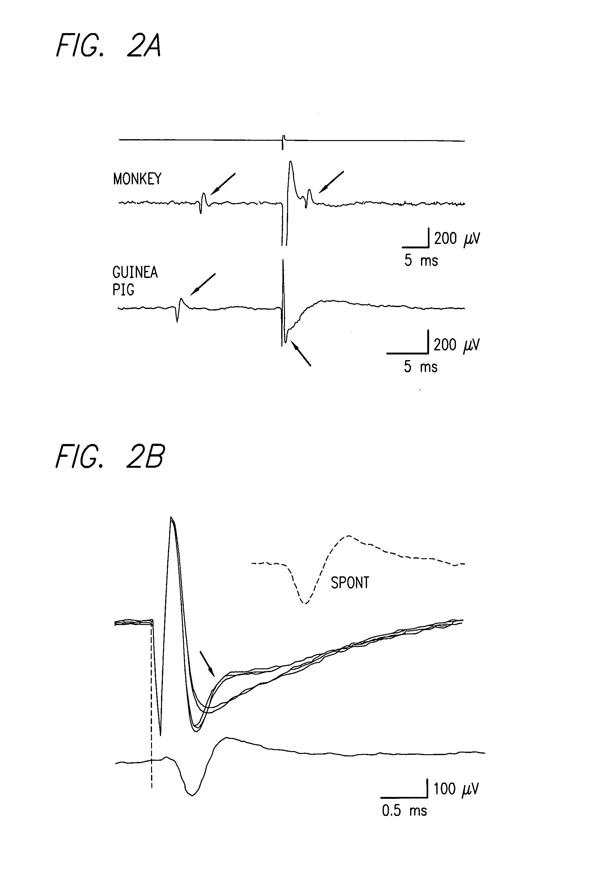
Existing epiretinal implants for the blind are designed to electrically stimulate large groups of surviving retinal neurons using a small number of electrodes with diameters of several hundred μm. To increase the spatial resolution of artificial sight, electrodes much smaller than those currently in use are desirable. In this study we stimulated and recorded ganglion cells in isolated pieces of rat, guinea pig, and monkey retina. We utilized micro-fabricated hexagonal arrays of 61 platinum disk electrodes with diameters between 6 and 25 μm, spaced 60 μm apart. Charge-balanced current pulses evoked one or two spikes at latencies as short as 0.2 ms, and typically only one or a few recorded ganglion cells were stimulated. Application of several synaptic blockers did not abolish the evoked responses, implying direct activation of ganglion cells. Threshold charge densities were typically below 0.1 mC / cm2 for a pulse duration of 100 μs, corresponding to charge thresholds of less than 100 pC. Stimulation remained effective after several hours and at high frequencies. To demonstrate that closely spaced electrodes can elicit independent ganglion cell responses, we utilized the multi-electrode array to stimulate several nearby ganglion cells simultaneously. From these data we conclude that electrical stimulation of mammalian retina with small-diameter electrode arrays is achievable and can provide high temporal and spatial precision at low charge densities. We review previous epiretinal stimulation studies and discuss our results in the context of 32 other publications, comparing threshold parameters and safety limits.

Description

CROSS REFERENCE TO RELATED APPLICATIONS [0001] This application is related to and claims benefit of US provisional application 60 / 733,2005, for Electrical Stimulation of Mammalian Retinal Ganglion Cells with Multi-Electrode Arrays filed Nov. 3, 2005. This application is related to and incorporates by reference, U.S. patent application Ser. No. 11 / 207,644Flexible Circuit Electrode Array filed Aug. 19, 2005.GOVERNMENT RIGHTS NOTICE [0002] This invention was made with government support under grant No. R24EY12893-01, awarded by the National Institutes of Health. The government has certain rights in the invention.FIELD OF THE INVENTION [0003] The present invention is generally directed to neural stimulation and more specifically to an improved method of providing artificial vision through electrical stimulation of visual neurons. BACKGROUND OF THE INVENTION [0004] In 1755 LeRoy passed the discharge of a Leyden jar through the orbit of a man who was blind from cataract and the patient sa...

Claims


Application Information

Patent Timeline
Patent Type & Authority Applications(United States)
IPC IPC(8): A61N1/18
CPCY10T29/49117A61N1/36046
Inventor GREENBERG, ROBERT J.MCMAHON, MATTHEW J.SEKIRNJAK, CHRISCHICHILNISKY, E.J.
Owner SALK INST FOR BIOLOGICAL STUDIES
Why Eureka
Try Eureka