
Energy-filtering cathode lens microscopy instrument

a cathode lens and electron microscopy technology, applied in instruments, material analysis using wave/particle radiation, nuclear engineering, etc., to achieve the effect of reducing the cost by a significant margin and eliminating the energy filter

Inactive Publication Date: 2007-08-30
IBM CORP
View PDF3 Cites 13 Cited by
  • Summary
  • Abstract
  • Description
  • Claims
  • Application Information

AI Technical Summary

Benefits of technology

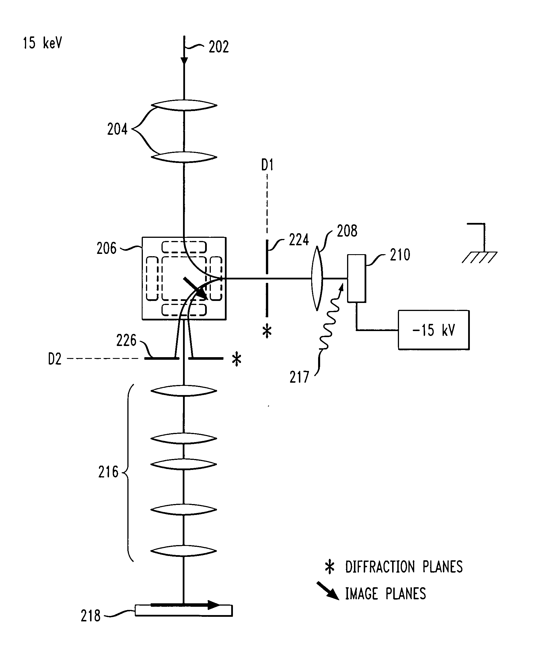
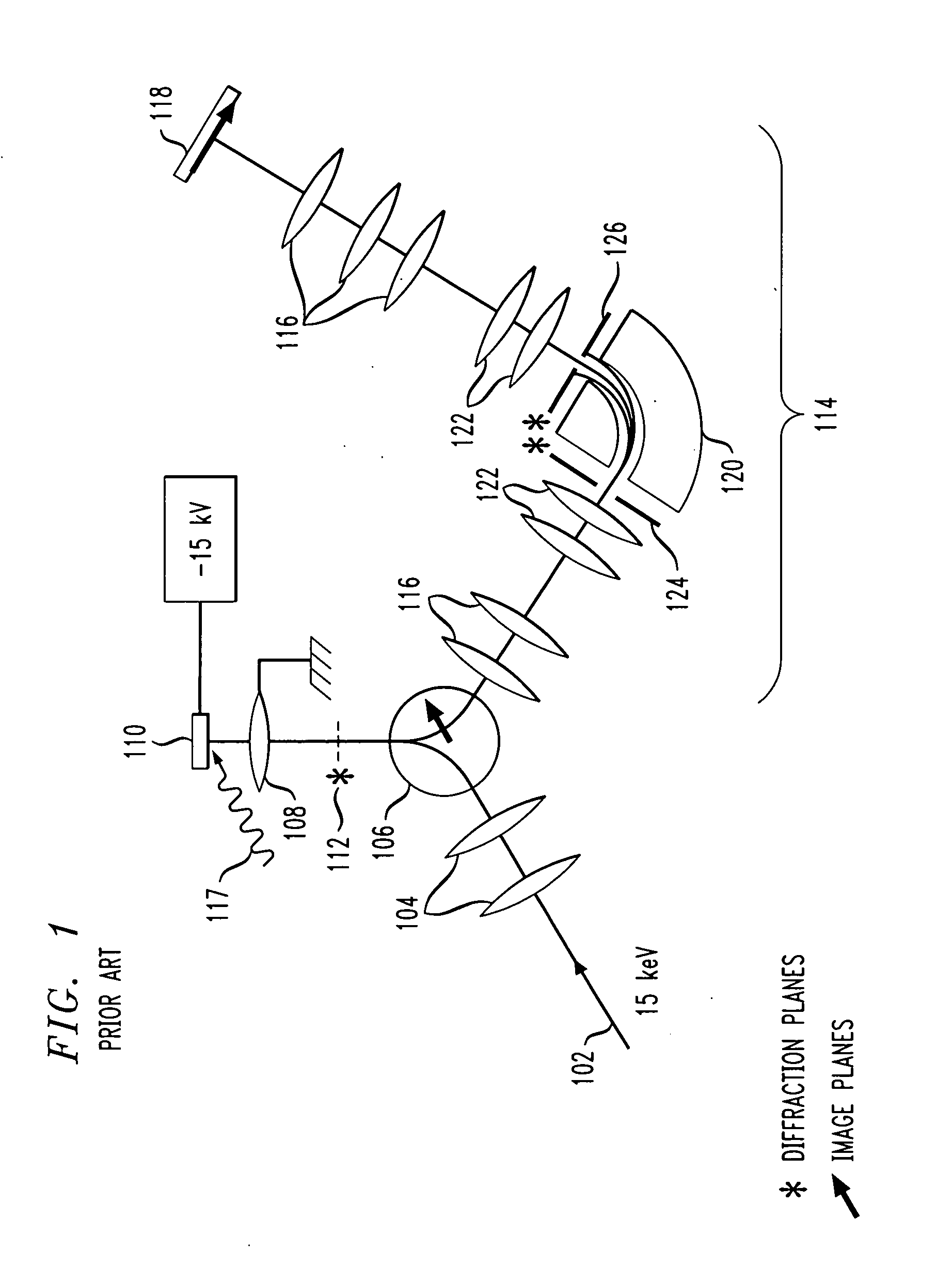
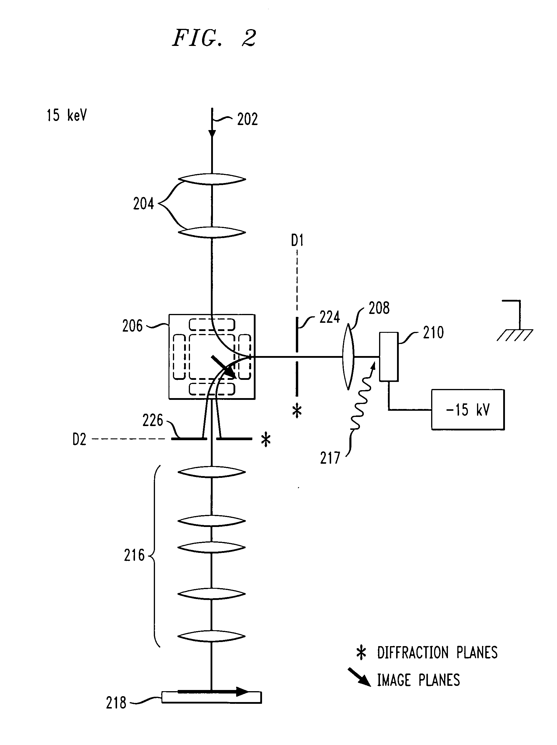
[0014] In another aspect of the present invention, a method of energy filtering in an electron microscopy instrument is provided. Energy filtering of the image and of the diffraction pattern is a desirable feature in combined LEEM / PEEM instruments. Present generation instruments realize energy filtering by the incorporation of an electron spectrometer and associated electron lenses in the projector column of the microscope, at great expense. The present invention describes a simplified solution which eliminates the energy filter, and reduces the cost by a significant margin.

Problems solved by technology

Present generation instruments realize energy filtering by the incorporation of an electron spectrometer and associated electron lenses in the projector column of the microscope, at great expense.

Method used


Image

  • Energy-filtering cathode lens microscopy instrument
  • Energy-filtering cathode lens microscopy instrument
  • Energy-filtering cathode lens microscopy instrument

Examples


Embodiment Construction

[0021] As will be illustrated in detail below, the present invention introduces a simplified energy filtering cathode lens microscopy instrument. The simplified electron microscopy instrument described in the embodiments of the present invention utilizes the magnetic deflector field at the heart of the LEEM / PEEM instrument, obviating the need for an electron spectrometer and associated coupling lenses. To enable energy filtering of either a real space image or a diffraction pattern, the backfocal plane of the objective lens is fitted with a movable and adjustable aperture.

[0022] In modern LEEM / PEEM instruments the magnetic deflector field consists of a prism array, more specifically, a combination of several electromagnets that produce desired electron optical properties. Most designs exhibit chromatic dispersion, in which electrons with different energies are deflected over different angles, but achromatic designs also exist. For the purposes of the present invention, a prism arra...


PUM

PropertyMeasurementUnit
energyaaaaaaaaaa
energyaaaaaaaaaa
angleaaaaaaaaaa

Abstract

An energy filtering microscopy instrument is provided. An objective lens is disposed for reception of electrons in order to form an electron diffraction pattern in a backfocal plane of the objective lens. An entrance aperture disposed in the backfocal plane of the objective lens for filtering a slice of the electron diffraction pattern. A magnetic deflector has an entrance plane and an exit plane. The entrance aperture is disposed in the entrance plane. The magnetic deflector is disposed to receive the slice of the electron diffraction pattern and project an energy dispersed electron diffraction pattern to the exit plane. An exit aperture is disposed in the exit plane of the magnetic deflector for selection of desired electron energy of the energy dispersed electron diffraction pattern.

Description

CROSS REFERENCE TO RELATED APPLICATIONS [0001] This application is related to the U.S. patent application Attorney Docket No. YOR920050577US1, entitled “Aberration-Correcting Cathode Lens Microscopy Instrument,” which is filed concurrently herewith and incorporated by reference herein.FIELD OF THE INVENTION [0002] The present invention relates generally to electron microscopy and, more particularly, to a simplified energy filtering electron microscopy instrument. BACKGROUND OF THE INVENTION [0003] Low energy electron microscopy (LEEM) and photo electron emission microscopy (PEEM) are both examples of cathode lens microscopy, in which a strong electric field is maintained between a sample under study and an objective lens of a microscope. In such instruments, the sample is considered the cathode and the objective lens is considered the anode. Electrons are reflected from the sample in the case of a LEEM instrument, or photo-emitted by the sample in case of a PEEM instrument, at low e...

Claims


Application Information

Patent Timeline
Patent Type & Authority Applications(United States)
IPC IPC(8): H01J37/05H01J49/46H01J37/26G01N23/225G01N23/227
CPCH01J37/05H01J37/252H01J2237/2544H01J2237/057H01J2237/2538H01J2237/0458
Inventor TROMP, RUDOLF M.
Owner IBM CORP
Learn More