Small-sized motor having polygonal outer shape

a small-sized motor and outer shape technology, applied in the direction of generator/motor, generator/motor, electrostatic generator/motor, etc., can solve the problems of reducing the efficiency of the motor, forming wasted spaces between the magnets, and accompanied by round shape, so as to reduce the waste of space around the motor, improve the rigidity of the side portions of the motor casing, and improve the effect of space efficiency

Active Publication Date: 2007-08-30
MABUCHI MOTOR
View PDF6 Cites 19 Cited by
  • Summary
  • Abstract
  • Description
  • Claims
  • Application Information

AI Technical Summary

Benefits of technology

[0011]An object of the present invention is to provide a small-sized motor having a polygonal outer shape which employs the polygonal outer shape in view of whirl-stop thereof and space efficiency and whose size can be reduced without involvement of a drop in performance thereof through reduction in weight and volume of a field magnet and efficient arrangement thereof.
[0012]Another object of the present invention is to provide a small-sized motor having a polygonal outer shape whose performance is improved through effective functioning of magnetic flux of a field magnet and whose productivity is enhanced through easy attachment of the field magnet into the yoke.
[0015]According to the present invention, the side portions of the motor casing (yoke) are formed flat, thereby providing a whirl-stop function at the time of mounting of the motor, and also reducing wasted space around the motor with a resultant improvement of space efficiency. Furthermore, since the field magnets are supported by the corner portions of the yoke, opposite ends of the individual side portions of the motor casing are pulled, whereby the rigidity of the side portions of the motor casing is enhanced; thus, vibration of the motor casing can be suppressed during rotation of the motor.
[0016]The field magnets are nonuniform in thickness such that the magnetic flux smoothly reduces, at their side portions, with a circumferential distance from their circumferential centers, whereby cogging torque can be lowered. Through employment of nonuniform thickness, the field magnets have at their circumferential centers such a thickness as to generate a magnetic field of sufficiently high intensity. Also, since the field magnets are pressed closely against the yoke at their circumferentially central portions, the intensity of magnetic field can be enhanced, thereby improving motor performance. Furthermore, clearances are formed between the field magnets and the side portions of the yoke so as to form air layers, whereby leakage of noise can be prevented.

Problems solved by technology

When a round motor is mounted in an apparatus, the round shape tends to be accompanied by wasted space within the apparatus.
Also, increasing the distance apparently causes a drop in motor performance.
Furthermore, wasted spaces are formed between the magnets.
Thus, as viewed on the cross section, disposing the magnets in the respective circumferentially central regions of the sides of the yoke raises the following problem: the magnets can be neither reduced in size nor arranged efficiently; consequently, the motor thickness (distance between diametrically opposed sides of the polygonal yoke) is increased, resulting in a failure to reduce the size of the motor.
However, in the case of the motor configuration shown in FIG. 8, making the field magnet fit corner portions of the yoke is not easy.
Since the intensity of magnetic field must be enhanced particularly at the apexes of magnetic poles of the field magnet, the presence of such clearances causes a drop in motor performance.
The shape of the field magnet is disadvantageous in that corner portions thereof fail to effectively function in relation to the rotor poles and that the weight and volume of the field magnet are increased, thereby causing a direct increase in cost.
The method of fixing the magnets through embedment in the yoke as shown in FIG. 9 involves the following problems: corner portions of the yoke are increased in thickness, so that the required amount of material is increased; and the complicated shape of the yoke causes an increase in the cost of machining a mold for the yoke.
Also, insertion of the magnets may cause cracking of the yoke.
Furthermore, a bonding process using an adhesive is required, and time for drying the adhesive is required as well.

Method used


Image

  • Small-sized motor having polygonal outer shape
  • Small-sized motor having polygonal outer shape
  • Small-sized motor having polygonal outer shape

Examples


Embodiment Construction

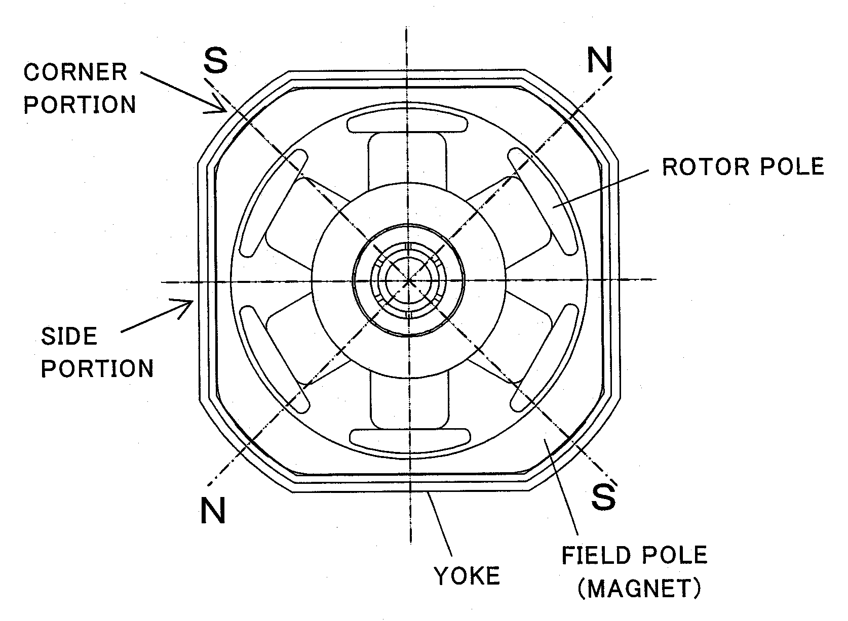
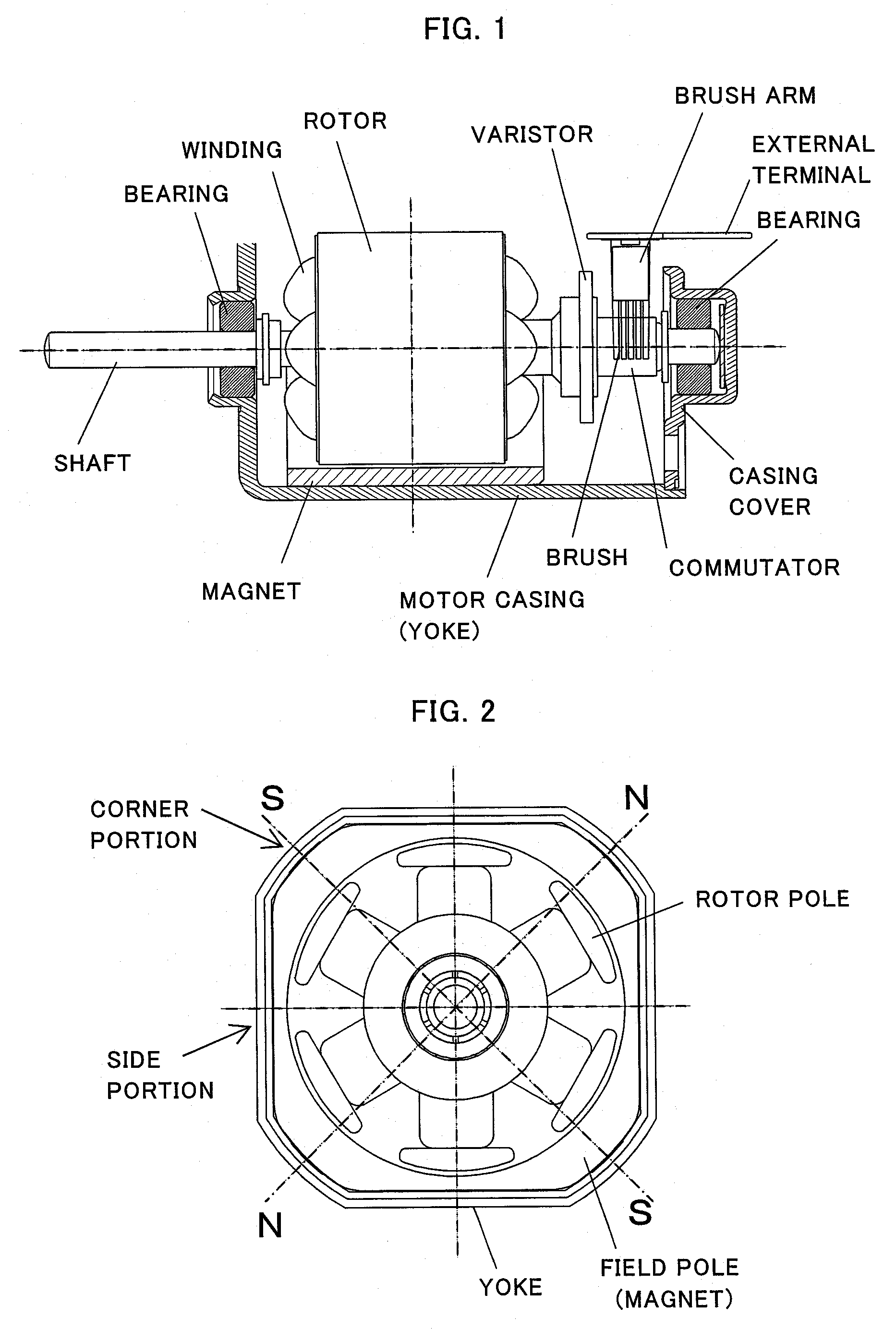
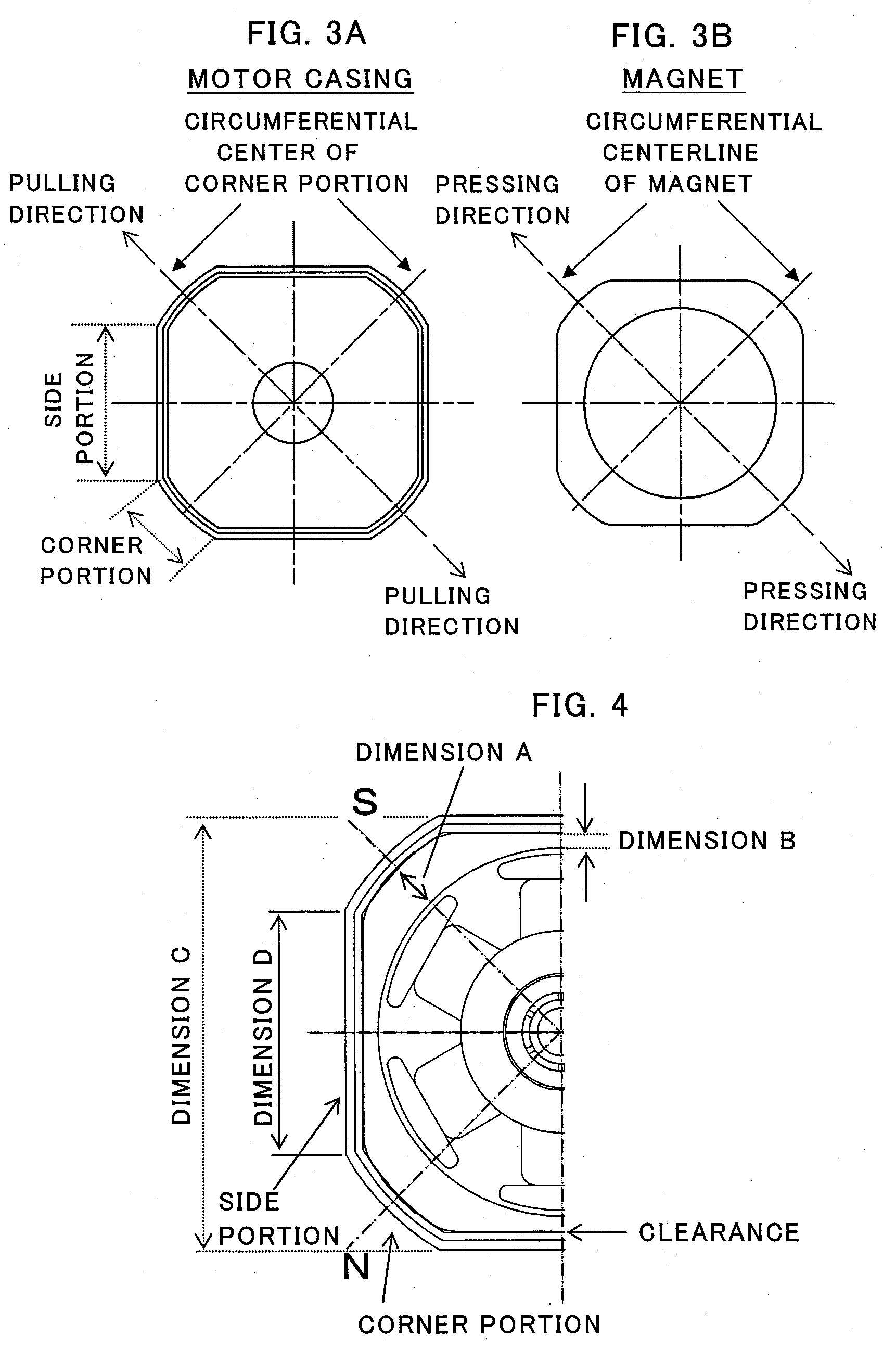
[0031]Embodiments of the present invention will next be described in detail with reference to the drawings. FIG. 1 is a partially sectional view showing the configuration of a small-sized motor having a polygonal outer shape according to an embodiment of the present invention; and FIG. 2 is a side view of the motor of FIG. 1 as viewed from a commutator side with a casing cover being removed. The following description discusses a small-sized motor having four field magnets and six rotor poles. However, the present invention can be applied to a small-sized motor having four or more field poles, such as four, six, or eight field poles, and three or more rotor poles.

[0032]As shown in FIGS. 1 and 2, a magnet is attached, from inside, to a motor casing, which is formed from a metal material into a closed-bottomed tubular shape by press working. A polygonal tubular portion of the motor casing of metal is a yoke, which serves as a magnetic path of the magnet. A casing cover is fitted to an ...


PUM


Abstract

A small-sized motor having a polygonal outer shape includes four or more field magnets attached to the inner surface of a motor casing made of metal. A tubular portion of the motor casing is formed into a polygonal tubular shape such that flat side portions equal in number to field poles, and flat or curved corner portions equal in number to the field poles and each being located between the adjacent side portions are sequentially joined together. The field magnets have a smaller thickness at portions corresponding to the side portions of the motor casing and a larger thickness at portions corresponding to the corner portions of the motor casing. The field magnets are fixed while coinciding in center position with the corresponding corner portions of the motor casing and while being pressed against the corresponding corner portions of the motor casing from inside.

Description

BACKGROUND OF THE INVENTION[0001]1. Field of the Invention[0002]The present invention relates to a small-sized motor having a polygonal outer shape for use in, for example, an air conditioner actuator or a motor-driven retractable mirror, and more particularly to a technique for mounting magnets for use as stator poles to the inner surface of a motor casing.[0003]2. Description of the Related Art[0004]As shown in FIG. 10A, an ordinary small-sized motor is such that a motor casing assumes a circular (round) tubular shape. When such a motor having a round outer shape (hereinafter, may be called a round motor) is to be mounted in an apparatus or on a wiring board, a whirl-stop must be employed for preventing rotation of the motor. When a round motor is mounted in an apparatus, the round shape tends to be accompanied by wasted space within the apparatus. In order to avoid rotation of a motor in relation to a mounting surface or to improve space efficiency, there is known impartment of a...

Claims


Application Information

Patent Timeline
Patent Type & Authority Applications(United States)
IPC IPC(8): H02K5/00H02K23/04H02N1/00
CPCH02K23/04H02K1/17
Inventor UENISHI, EIJINEMOTO, NOBUYUKI
Owner MABUCHI MOTOR
Why Eureka
Try Eureka