
Stirling-cycle cooling device with external rotor motor

Pending Publication Date: 2020-07-02
THALES SA
View PDF4 Cites 0 Cited by
  • Summary
  • Abstract
  • Description
  • Claims
  • Application Information

AI Technical Summary

Benefits of technology

The patent describes a motor design that can generate more torque with a smaller size and improve cooling efficiency. Additionally, the use of an external rotor motor can prevent the detachment of magnets during operation. This design also avoids the need for specific holding means that can decrease motor performance.

Problems solved by technology

An internal rotor motor presents the risk of detachment of the magnets during rotation of the motor owing to the centrifugal force that tends to tear the magnets from their support.
However, in an external rotor motor comprising magnets, the latter tend to be pressed against the bottom of their housing, thereby avoiding the implementation of specific means for holding the magnets, such as specific magnet holding rings.
In an internal rotor motor, such holding means tend also to increase the gap between the rotor and the stator, which gives rise to a drop in the performance of the motor.

Method used


Image

  • Stirling-cycle cooling device with external rotor motor
  • Stirling-cycle cooling device with external rotor motor
  • Stirling-cycle cooling device with external rotor motor

Examples


first embodiment

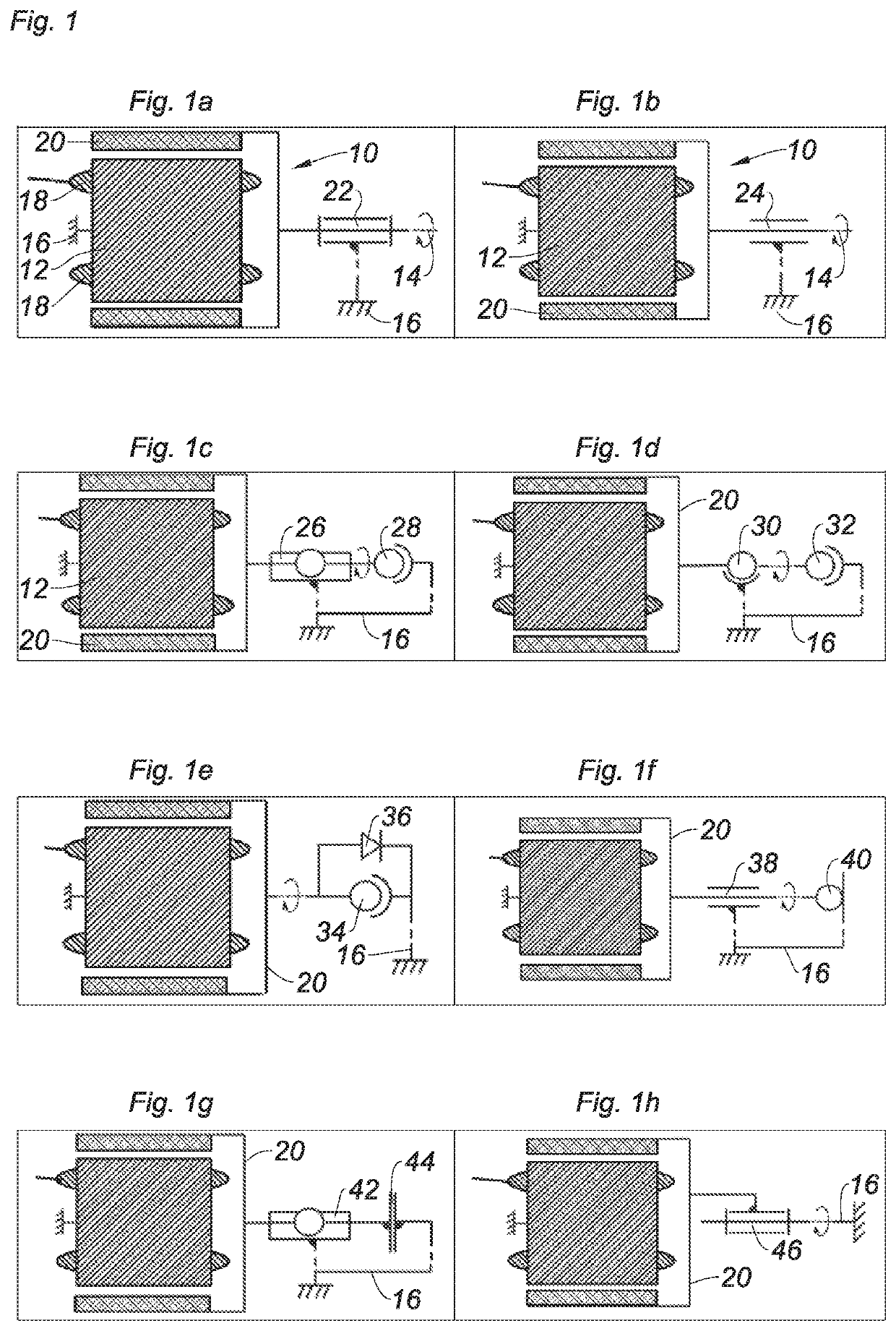
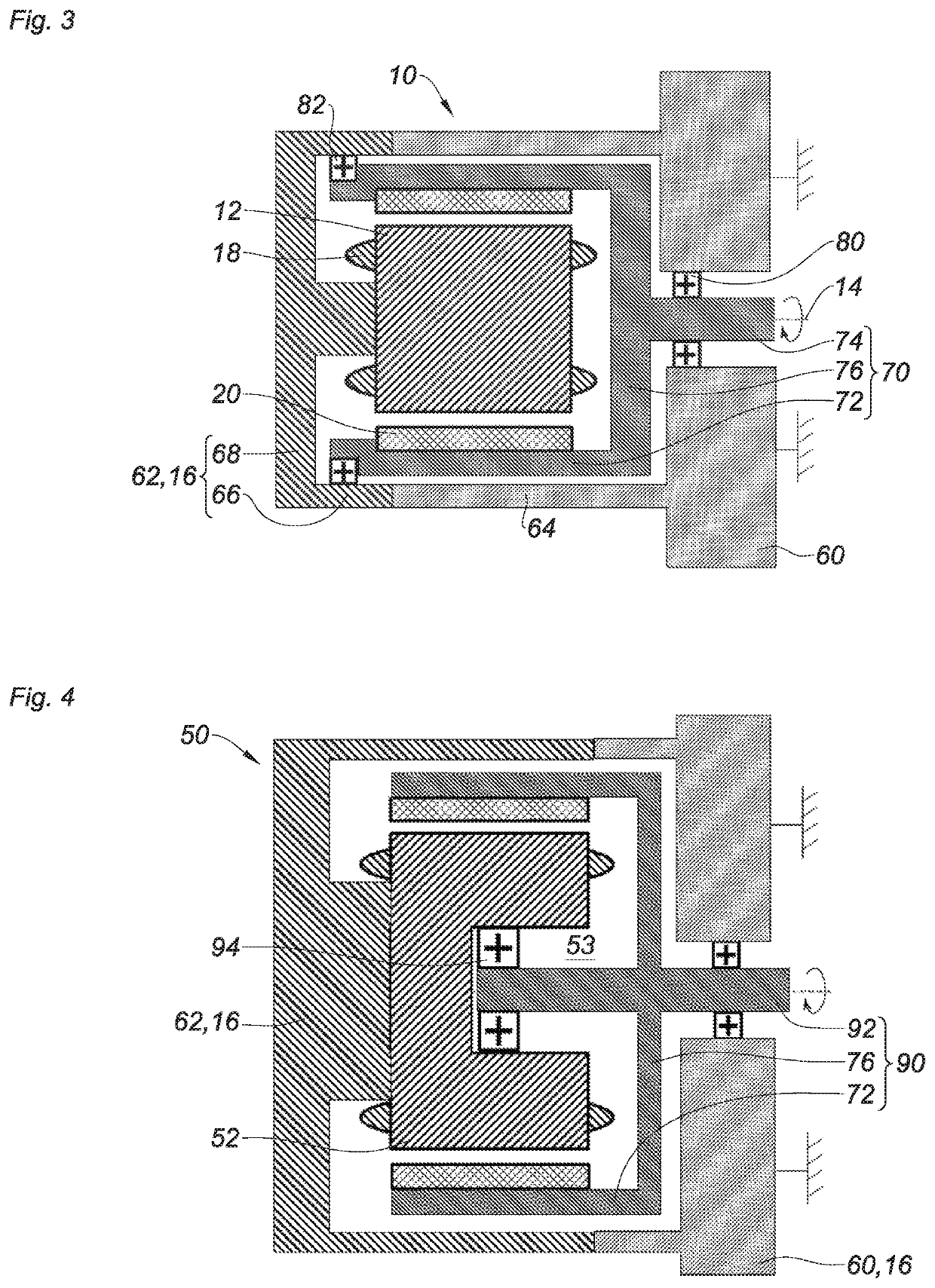
[0061]FIG. 3 shows a refrigeration device according to the invention. The device comprises the external rotor motor 10, the stator 12 of which has a solid cylindrical form. The housing 16 of the device is produced in the form of a plurality of mechanical components belonging to the same equivalence class. In other words, the different components of the housing 16 have no degree of freedom between them. The housing 16 comprises a body 60 of the compressor (not shown) and a cover 62 fixed to the body 60. The housing 16 forms a shell of the motor 10. The motor 10 has a globally cylindrical form about the axis 14. The body 60 comprises a tubular section 64 of axis 14 inside which the motor 10 is inserted. The cover 62 also comprises a tubular part 66 extending in the extension of the tubular section 64 and fixed thereto. The cover 62 comprises a flank 68 extending perpendicularly to the axis 14. The flank 68 closes the tubular part 66. In practice, the tubular section 64 may extend as f...

second embodiment

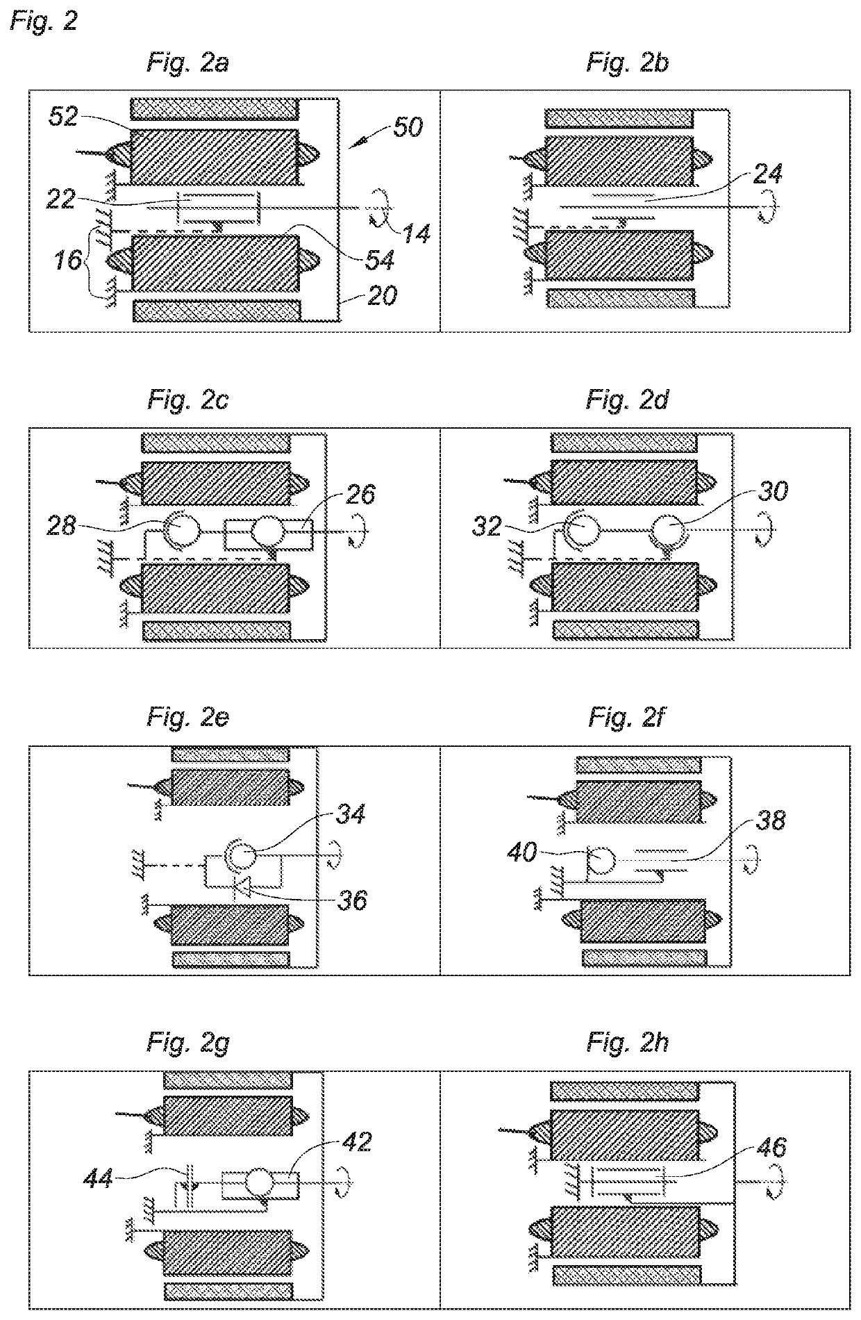
[0066]FIG. 4 shows a refrigeration device according to the invention. The device comprises an external rotor motor, the stator of which has a cylindrical form that is in part open along the axis 14 of rotation of the motor. This form of the stator is intermediate between the schematic representations of FIGS. 1a to 1h on the one hand and those of FIGS. 2a to 2h. The references of FIGS. 2a to 2h are resumed for FIG. 4: 50 for the motor, 52 for the stator and 20 for the rotor. Here, the housing 16 is formed by the body 60 and the cover 62 on which the stator 52 is fixed. The motor 50 comprises a drive shaft 90 in which there is the tube 72 and the web 76. Unlike the drive shaft 70, the drive shaft 90 comprises a solid bearing surface 92 partially traversing the opening 53 of the stator 52.

[0067]The bearing 80 lies between the bearing surface 92 and the body 60. In FIG. 4, a second bearing 94 is arranged between the stator 52 and the bearing surface 92 in the bottom of the opening 53. ...


PUM


Abstract

A cooling device implementing a stirling-type thermodynamic cycle includes a compressor with a reciprocating piston driven by an electric motor rotating about an axis via a crankshaft. The electric motor comprises an internal stator and an external rotor and is connected to the crankshaft via a link with at least one degree of freedom in rotation about the axis of the electric motor.

Description

CROSS-REFERENCE TO RELATED APPLICATIONS[0001]This application claims priority to foreign French patent application No. FR 1874264, filed on Dec. 28, 2018, the disclosure of which is incorporated by reference in its entirety.FIELD OF THE INVENTION[0002]The invention relates to a cooling device implementing a reverse Stirling-type thermodynamic cycle. Such a device is, for example, described in patent U.S. Pat. No. 4,365,982. Cooling is achieved by means of a coolant fluid circulating in a circuit comprising, principally, a compressor and a regenerator used as heat exchanger. The compressor comprises a piston that is movable in translation in a cylinder. The regenerator comprises a regeneration piston that is likewise movable in a second cylinder. The regenerator is sometimes called: “displacer”. The two pistons are each driven by a connecting rod / crank arm, both actuated by a crankshaft. The crankshaft is driven in rotation by a rotary motor.BACKGROUND[0003]In a known manner, the rev...

Claims


Application Information

Patent Timeline
IPC IPC(8): F25B9/14F04B53/00F04B17/03
CPCF25B2309/003F25B2327/00F25B9/14F04B53/006F04B17/03F04B35/04H02K1/2786H02K1/187H02K7/1815F25B2309/001F02G1/044F04B1/148F02G1/055F02G1/057H02K7/003H02K7/08F02G2244/50F02G2270/10H02K7/1016
Inventor SACAU, MIKELMARTIN, JEAN-YVESLE BORDAYS, JULIEN
Owner THALES SA
Learn More