Control device for permanent magnet synchronous motor

Inactive Publication Date: 2007-08-30
MITSUBISHI ELECTRIC CORP
View PDF16 Cites 28 Cited by
  • Summary
  • Abstract
  • Description
  • Claims
  • Application Information

AI Technical Summary

Benefits of technology

[0015] In the above configuration, when the recovering electric power cannot be completely consumed in the motor, the switching device is activated t

Problems solved by technology

However, when the conventional control device for permanent magnet synchronous motor is operated without limiting d-axis current therethrough, there has

Method used


Image

  • Control device for permanent magnet synchronous motor
  • Control device for permanent magnet synchronous motor
  • Control device for permanent magnet synchronous motor

Examples


embodiment 1

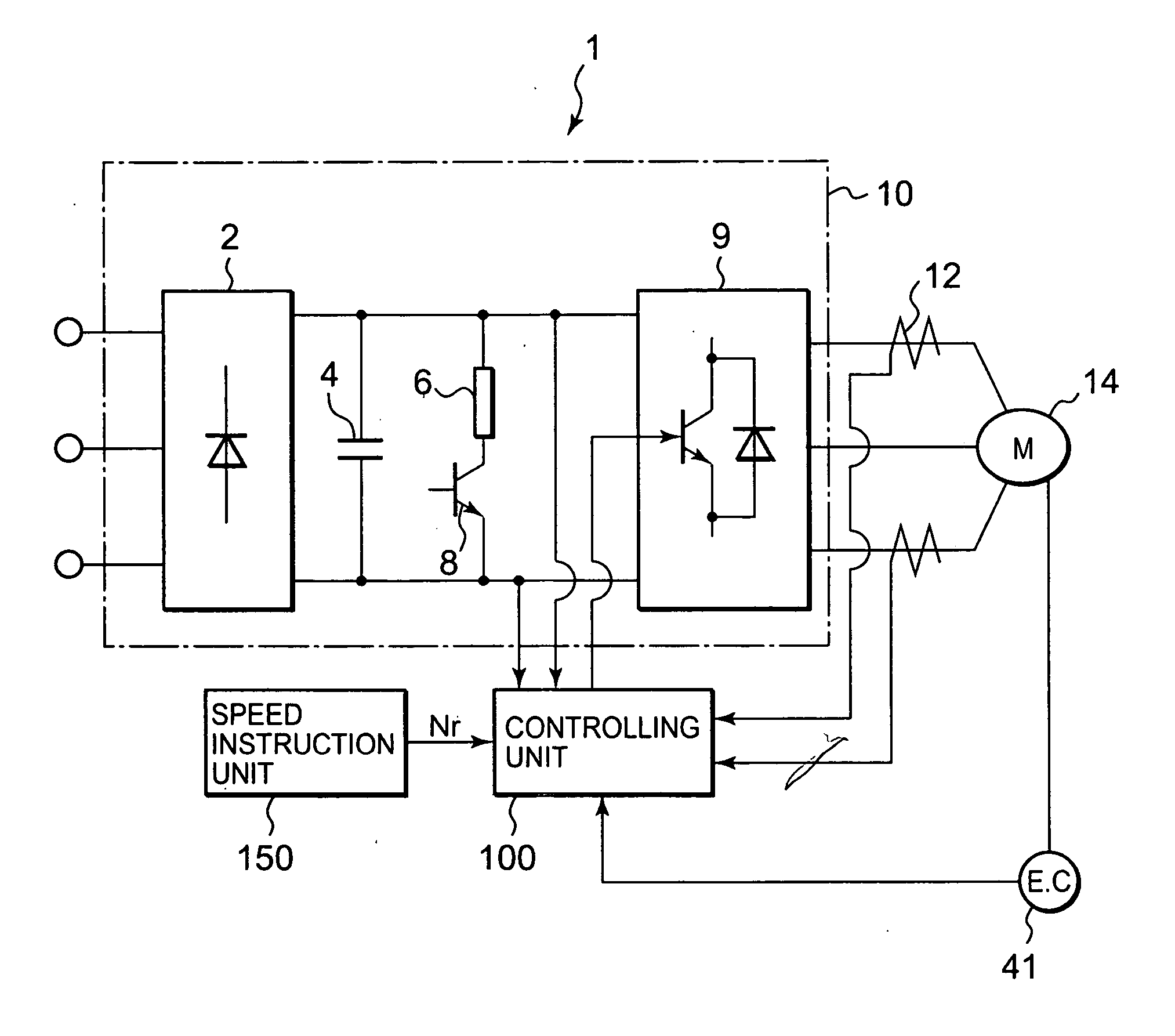
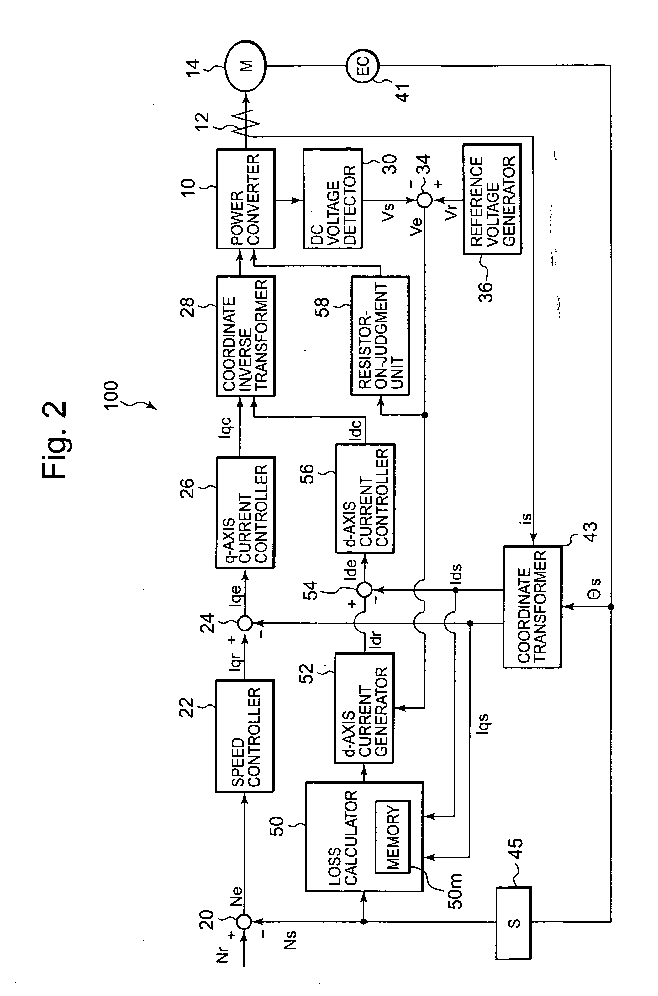
[0022] An embodiment according to this invention is explained, using FIG. 1 through FIG. 3. FIG. 1 is a whole block diagram illustrating a control device for a permanent magnet synchronous motor, FIG. 2 is a detailed block diagram illustrating the controlling device shown in FIG. 1, and FIG. 3 is a detailed block diagram illustrating the loss calculator shown in FIG. 2.

[0023] In FIG. 1 through FIG. 3, the control device for the motor includes a power converter 10, a controlling unit 100, a current detector (a current detecting means) 12 that detects current flowing into a motor 14 and inputs into the controlling unit 100 a current detecting signal is, and an encoder 41 that detects the rotational position of the motor 14 and inputs into the controlling unit 100 the position detection signal θs, and a speed instruction signal Nr, generated by a speed instruction unit 150, is inputted into the controlling unit 100.

[0024] The power converter 10 includes a converter 2 for converting t...

embodiment 2

[0049] Another aspect of an embodiment according to this invention is explained, using FIG. 5. FIG. 5 is a block, diagram illustrating an entire control device, for the motor, according to this aspect of the embodiment. In FIG. 5, the identical numerals with the ones in FIG. 2 refer to the identical parts, and those explanations are eliminated.

[0050] Given In as the rated current of the transistor configuring the inverter 9, there is an relation between the q-axis current and the d-axis current that flow into the motor 14, as described below.

In=(iq2+id2)1 / 2

[0051] From the above equation, the maximum flowable d-axis current instruction signal idmax is given below.

idmax=(In2+id2)1 / 2

[0052] As is shown in FIG. 5, a current limiter 103 that limits current in the d-axis current generator 52 is provided in order to prevent the d-axis current from exceeding the idmax.

[0053] Because the above-described control device for the motor is provided, so that current flows through the inverter...

embodiment 3

[0054] Still another aspect of an embodiment according to this invention is explained, using FIG. 6. FIG. 6 is a block diagram for calculating temperature rise in the motor windings, according to this aspect of the embodiment. In FIG. 6, the identical numerals with the ones in FIG. 3 refer to the identical parts and those explanations are eliminated.

[0055] In FIG. 6, the functional block for calculating temperature rise in the motor 14 windings includes: a primary temperature estimator 317 for calculating to output temperature rise in the winding of the motor 14 itself from the inputted average copper loss Pcave, being outputted from the average copper loss calculator 217; a secondary estimator 313 for calculating temperature rise in the iron core of the motor 14 from the inputted average iron loss Piave, being outputted from the average iron loss calculator 213; and an adder 315 for estimating temperature rise in the winding by adding the temperature rise in the winding itself and...


PUM


Abstract

A control device for a permanent magnet synchronous motor includes: an inverter 9 for converting inputted DC voltage into AC voltage of variable-voltage and variable-frequency, and driving a motor 14 with the AC voltage; a speed controller 22 for generating, in accordance with a speed instruction signal, a q-axis current component orthogonal to the magnetic field of the motor 14; a loss calculating means 50 for calculating a loss by summing a copper loss and an iron loss in the motor 14; a d-axis current generating means 52 for generating, in accordance with the value that is the motor's rated loss decreased by the loss, a d-axis current instruction signal to flow into the motor 14; and a resistor-on-judgment unit 58 for judging, from the DC voltage, whether or not the motor 14 operates in its recovery state and activating the d-axis current generator 52 while in the recovery state.

Description

TECHNICAL FIELD [0001] The present invention relates to control devices, for permanent magnet synchronous motors, that control, considering the motor's load conditions, so as to allow its recovering electric power to be consumed by the motor. [0002] A conventional control device for permanent magnet synchronous motor has been disclosed in Japanese Patent Laid-Open No. 2001-95300 as follows; the control device includes an inverter for converting DC voltage to alternating current of variable voltage and variable frequency, a permanent magnet synchronous motor to which electricity is fed from the inverter, a speed control unit for generating a speed instruction signal, a speed controller for generating a torque instruction signal in order to make the motor's speed respond to the speed instruction signal, a q-axis current instructing unit for generating an instruction signal for a current component (a q-axis current component) orthogonal to the magnetic field of the motor, a d-axis curr...

Claims


Application Information

Patent Timeline
IPC IPC(8): H02P1/46H02P21/00H02P21/02H02P21/06H02P21/14
CPCH02P21/02H02P2207/05H02P21/06
Inventor ITOU, NOBUOHORII, KEITA
Owner MITSUBISHI ELECTRIC CORP
Why Eureka
Try Eureka