Controller for an electric four-wheel-drive vehicle

Inactive Publication Date: 2007-08-30
HITACHI LTD +1
View PDF9 Cites 22 Cited by
  • Summary
  • Abstract
  • Description
  • Claims
  • Application Information

AI Technical Summary

Benefits of technology

[0006]It is an object of the present invention to provide a controller for an electric four-wheel-drive vehicle, which is capable of minimizing torque changes and consuming excessive power even when the excessive power is generated by the generator.
[0019]Even when excessive power is generated by the generator, the present invention makes it possible to reduce torque changes and consume the excessive power.

Problems solved by technology

However, the method disclosed in JP-A-2005-143285 consumes the excessive power as motor torque.
Therefore, the resulting generated torque is essentially more than adequate for a vehicle run.
Thus, the vehicle may change its behavior and fail to deliver its full-expected driving performance.
It is also anticipated that tires may slip depending the road surface conditions.
When the power generated by the generator is larger than the power consumption of the inverter and the AC motor to generate excessive power, the control means consumes the excessive power by increasing a loss in the AC motor.

Method used


Image

  • Controller for an electric four-wheel-drive vehicle
  • Controller for an electric four-wheel-drive vehicle
  • Controller for an electric four-wheel-drive vehicle

Examples


first embodiment

[0034]A controller for an electric four-wheel-drive vehicle according to the present invention will now be described with reference to FIGS. 1 to 6.

[0035]First of all, the system configuration for an electric four-wheel-drive vehicle to which the controller according to the first embodiment of the present invention is applied will be described with reference to FIG. 1.

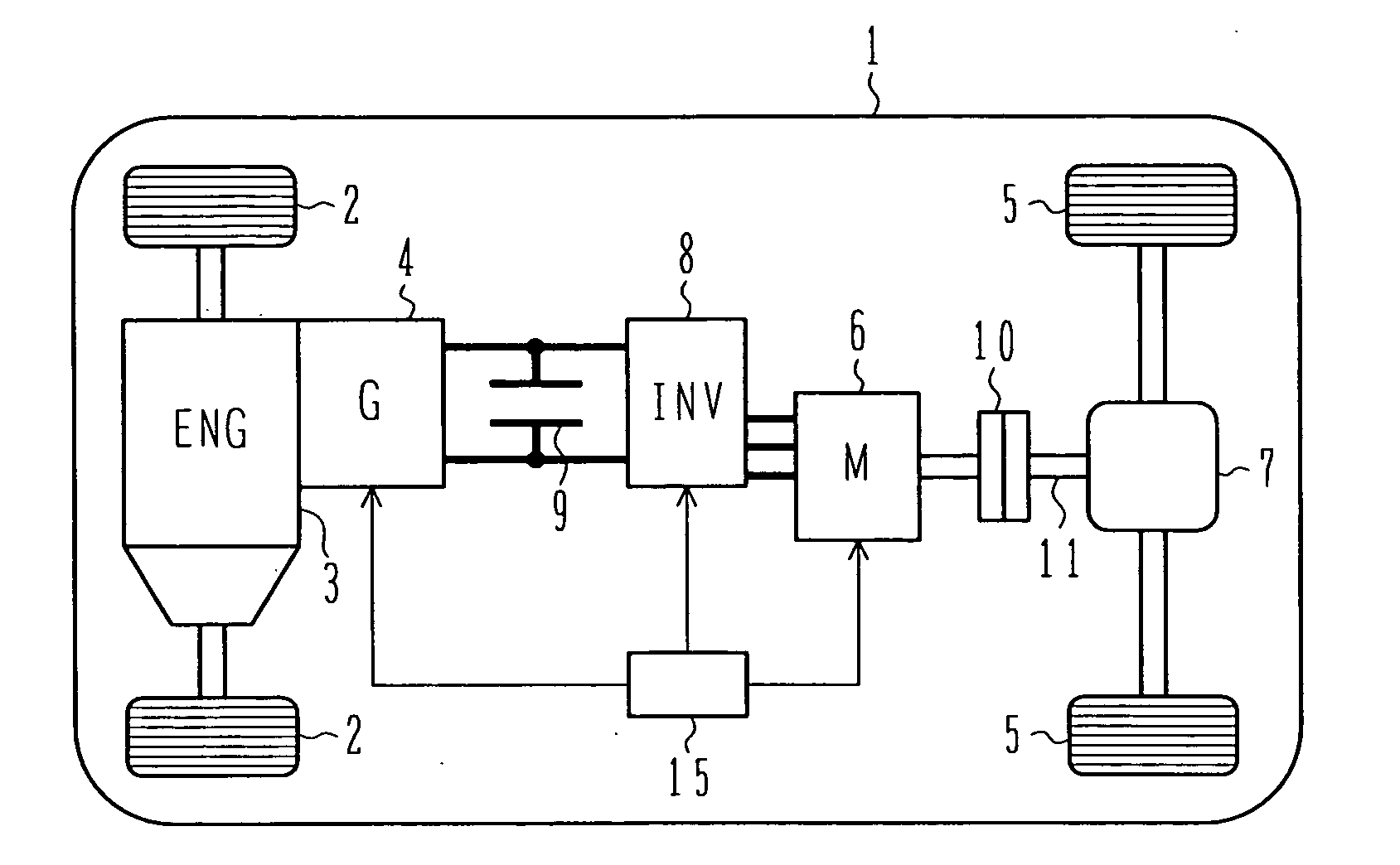
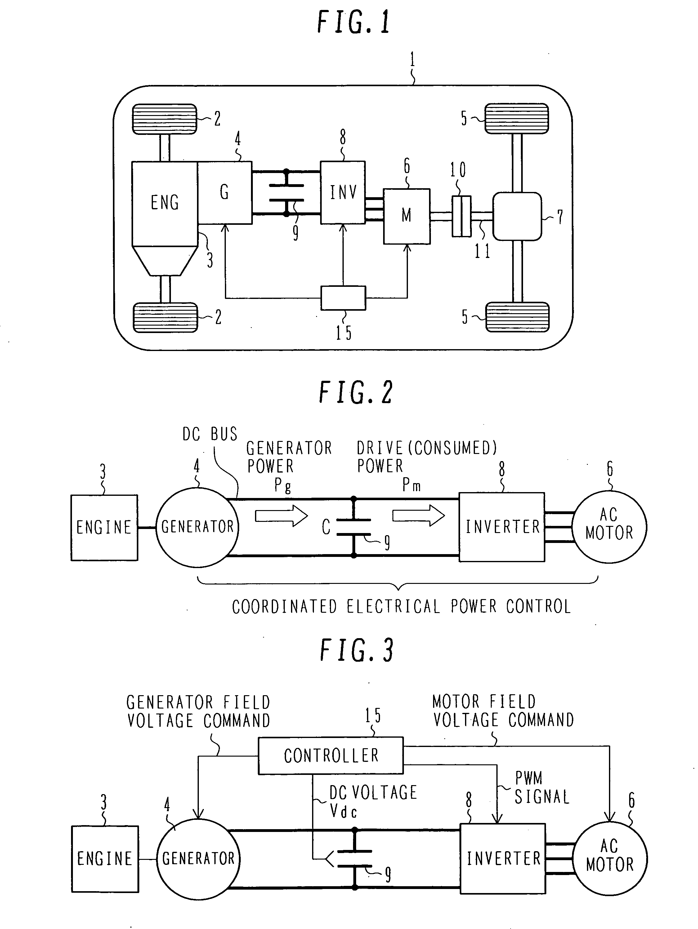
[0036]FIG. 1 is a system configuration diagram illustrating the electric four-wheel-drive vehicle to which the controller according to the first embodiment of the present invention is applied.

[0037]In the electric four-wheel-drive vehicle 1, a dedicated generator 4 is connected to an engine 3 that drives front wheels 2. An AC motor 6 generates motive energy on the basis of power generated by the generator 4. The motive energy generated by the AC motor 6 drives rear wheels 5. This motive energy is distributed to the right and left by a differential gear unit 7 and transmitted to the rear wheels 5.

[0038]A 4WD clutch 10, ...

second embodiment

[0084]FIG. 7 is a block diagram illustrating the configuration of a current command determination unit that is included in the motor control unit for use in the controller according to the present invention. Elements shown in FIGS. 6 and 7 are designated by the same reference numerals when they are identical with each other.

[0085]The embodiment shown in FIG. 6 calculates the generated power Pg and input power Pm from respective physical quantities. However, the use of such a calculation method may affect the calculation load on the controller 15. Therefore, the present embodiment performs a simplified, proper process. The process that the present embodiment performs to consume the excessive power is basically based on the voltage of the capacitor 9.

[0086]The current command determination unit F10X includes an excessive power calculation unit F10C′, the required discharge power calculation unit F10D, the motor current equivalent calculation unit F10E, the current command calculation ...

third embodiment

[0100]FIG. 8 is a block diagram illustrating the configuration of a current command determination unit that is included in the motor control unit for use in the controller according to the present invention. Elements shown in FIGS. 6 and 8 are designated by the same reference numerals when they are identical with each other.

[0101]The current command determination unit F10Y included in the present embodiment differs from the current command determination unit F10 shown in FIG. 6 in that a current limiting unit F10H is furnished and positioned after the current equivalent calculation unit F10G. In the examples shown in FIGS. 6 and 7, the d-axis current is increased to increase the motor loss. However, the d-axis current cannot be allowed to flow in excess of the maximum allowable current for the inverter and motor. In the present embodiment, therefore, the current limiting unit F10H is furnished to limit the motor loss, which should be increased, when the motor current is smaller than...


PUM


Abstract

An object of the present invention is to provide a controller for an electric four-wheel-drive vehicle, which is capable of minimizing torque changes and consuming excessive power even when the excessive power is generated by a generator. A motor control unit causes an AC motor to generate desired torque by controlling an inverter. When the power generated by the generator exceeds the power consumed by the inverter and AC motor to generate excessive power, a current command determination unit in the motor control unit consumes the excessive power by increasing a loss in the AC motor.

Description

BACKGROUND OF THE INVENTION[0001]The present invention relates to a controller for an electric four-wheel-drive vehicle that runs while its wheels are driven by engine-generated driving force and its other wheels are driven by motor-generated driving force.[0002]In recent years, an increasing number of automobiles are motor-driven. They are electric automobiles, hybrid automobiles, and other environment-responsive automobiles and electric four-wheel-drive vehicles. These vehicles are mainly characterized by the fact that they carry a battery or engine-driven generator and use the power generated by the battery or generator to drive their wheels with a motor. When front wheels of a vehicle are motor-driven, the vehicle is operated as a front-wheel-drive vehicle so that the motor assists an engine shaft with torque. When, on the other hand, rear wheels of the vehicle are motor-driven, the vehicle is operated as an electric four-wheel-drive vehicle because the front wheels are engine-d...

Claims


Application Information

Patent Timeline
IPC IPC(8): H02P27/04B60K6/34B60L50/10B60L50/15B60L50/16
CPCB60L11/123B60L11/14Y02T10/7077Y02T10/6217B60L2240/525B60L50/16B60L50/61Y02T10/62Y02T10/70Y02T10/7072
Inventor KANEKO, SATORUIZUMI, SHIHOYAMAMOTO, TATSUYUKIKATSUHAMA, KENTAAKAISHI, SHIGERUMATSUNAGA, YASUOSUGITA, HIDEHIKO
Owner HITACHI LTD
Why Eureka
Try Eureka