

Piezoelectric element, vibrator, vibration wave motor, optical device, and electronic device
a technology of vibration wave motor and piezoelectric element, which is applied in the direction of instruments, printers, cameras, etc., can solve the problems of reducing piezoelectric characteristics, affecting the operation of the electronic device, etc., and achieves the effect of insufficient vibration velocity and high efficiency
- Summary
- Abstract
- Description
- Claims
- Application Information
AI Technical Summary
Benefits of technology
Problems solved by technology
Method used
Image

Examples
example 1
[0108]First, a powdered barium titanate-based material serving as a starting material of a piezoelectric material layer was prepared.
[0109]Specifically, barium carbonate (BaCO3), calcium carbonate (CaCO3), titanium oxide (TiO2), zirconium oxide (ZrO2), and trimangantetraoxid (Mn3O4) were weighed in such a manner that an x value which is a molar ratio of Ba to the total of Ba and Ca was 0.13, a y value which is a molar ratio of Zr to the total of Ti and Zr was 0.03, and the Mn content was 0.30 part by weight in terms of metal based on 100 parts by weight of an oxide containing Ba, Ca, Ti, and Zr, followed by mixing. The mixed powder was calcined at 900° C. for 4 hours to give calcined powder containing the barium titanate-based material.
[0110]To 100 parts by weight of the calcined powder, 0.1 part by weight of an assistant was added. For the assistant, a mixture of particulate SiO2, B2O3, Al2O3, and Na2CO3 having an average particle diameter of 1.0 μm was used. The weight ratio of Si...
examples 2 to 7
[0128]Piezoelectric elements of the present disclosure were obtained in the same manner as in Example 1, except changing the raw material mixing ratio, the green sheet thickness, the Ag / Pd ratio of the conductive paste, and the highest firing temperature of the laminate.
[0129]When the composition of the piezoelectric material portion was evaluated by ICP optical emission spectroscopy, the weighed compositions of the components of Ba, Ca, Ti, Zr, and Mn and the compositions after sintering coincide with each other in all the piezoelectric elements. The lead components contained in the piezoelectric elements and the piezoelectric material layers were less than 10 ppm in all the piezoelectric elements. The manufacturing conditions of the piezoelectric elements are given in Table 1.
[0130]The TP, the TE, the DG, the LV, the Ra, the d33, and the dielectric loss tangent of the piezoelectric elements were measured in the same manner as in Example 1. The measurement results of the parameters...
example 8
[0132]A piezoelectric element was obtained in the same manner as in Example 1, except adding 0.1 part by weight in terms of solid content of hollow silica particles in the form of an IPA dispersion liquid based on 100 parts by weight of calcined powder in addition to the mixture of SiO2, B2O3, Al2O3, and Na2CO3 as the assistant to the calcined powder.
[0133]When the composition of a piezoelectric material portion was evaluated by ICP optical emission spectroscopy, the weighed compositions of the components of Ba, Ca, Ti, Zr, and Mn and the compositions after sintering coincide with each other. The lead components contained in the piezoelectric element and the piezoelectric material layer were about 3 ppm.
[0134]The TP, the TE, the DG, the LV, the Ra, the d33, and the dielectric loss tangent of the piezoelectric element were measured in the same manner as in Example 1. The measurement results of the parameters are given in Table 2. The PV determined in the same manner as in Example 1 w...
PUM
| Property | Measurement | Unit |
|---|---|---|
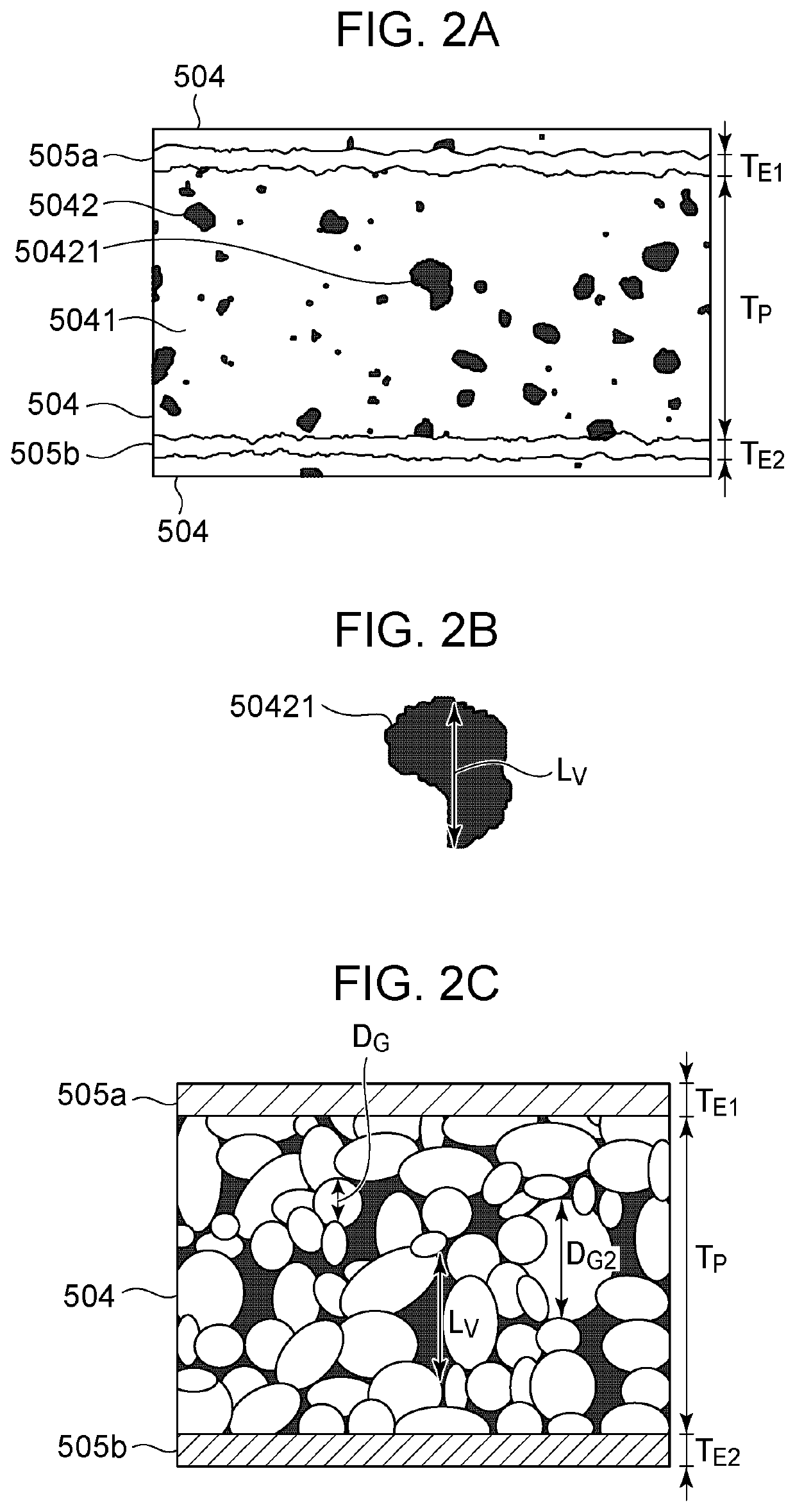
| circle-equivalent diameter DG | aaaaa | aaaaa |
| circle-equivalent diameter DG | aaaaa | aaaaa |
| roughness | aaaaa | aaaaa |
Abstract
Description
Claims
Application Information