Signal process system and method for the same and biological resistance detection device and element

a technology of biological resistance and process system, applied in the field of signal process technology, can solve the problems of not being able to implement biological impedance detection systems, consuming more hardware space, and consuming more power, etc., and achieves the effects of good integrated characteristic, excessive hardware, and excessive power consumption

Active Publication Date: 2015-12-17
NAT CHENG KUNG UNIV
View PDF0 Cites 1 Cited by
  • Summary
  • Abstract
  • Description
  • Claims
  • Application Information

AI Technical Summary

Benefits of technology

[0020]The signal process system and the method for the same and the biological impedance detection device and element of the invention may be applied to measure signal level difference and phase difference of different signals for further application in detection of biological impedance. In biological impedance detection, impedance information of a biological tissue may be derived by measuring a frequency response of said biological tissue to a stimulus signal (including signal gain (|Z|) and phase (Φ)), and said impedance information may be further utilized to be reference for syndrome diagnosis. Also, the signal process system and the method for the same and the biological impedance detection device and element of the invention have good integrated characteristic capable of solving conventional problems, including excessive hardware need of impedance detection device, excessive power consumption and complex design etc.

Problems solved by technology

However, more time was necessary to adjust balance of the bridge in measurement, such that it is not suitable for biological impedance that would change with time.
Moreover, this technology itself consumed higher power and more hardware space was needed for implementation.
Hence, this technology was not applicable to implantable or portable biological impedance detection system.
This would increase the complexity in implementing the circuit and increase the overall power consumption of the system.
As a result, it is not applicable to implantable or portable device.

Method used


Image

  • Signal process system and method for the same and biological resistance detection device and element
  • Signal process system and method for the same and biological resistance detection device and element
  • Signal process system and method for the same and biological resistance detection device and element

Examples


Embodiment Construction

[0027]Embodiments of the present invention will now be described in detail with reference to the accompanying drawings. The invention may, however, be embodied in many different forms and should not be construed as being limited to the embodiments set forth herein. Rather, these embodiments are provided so that this disclosure will be thorough and complete, and will fully convey the scope of the invention to those skilled in the art. In the drawings, the shapes and dimensions of elements may be exaggerated for clarity, and the same reference numerals will be used throughout to designate the same or like components.

[0028]It is noted that the signals mentioned in examples of the invention may be voltage, current or charge signals according to different implementation approaches.

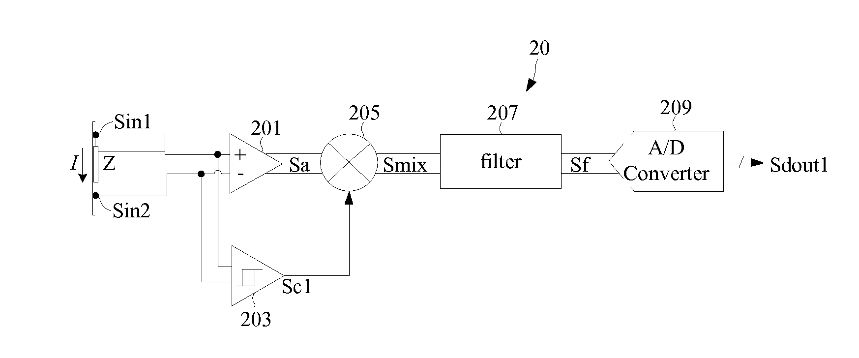
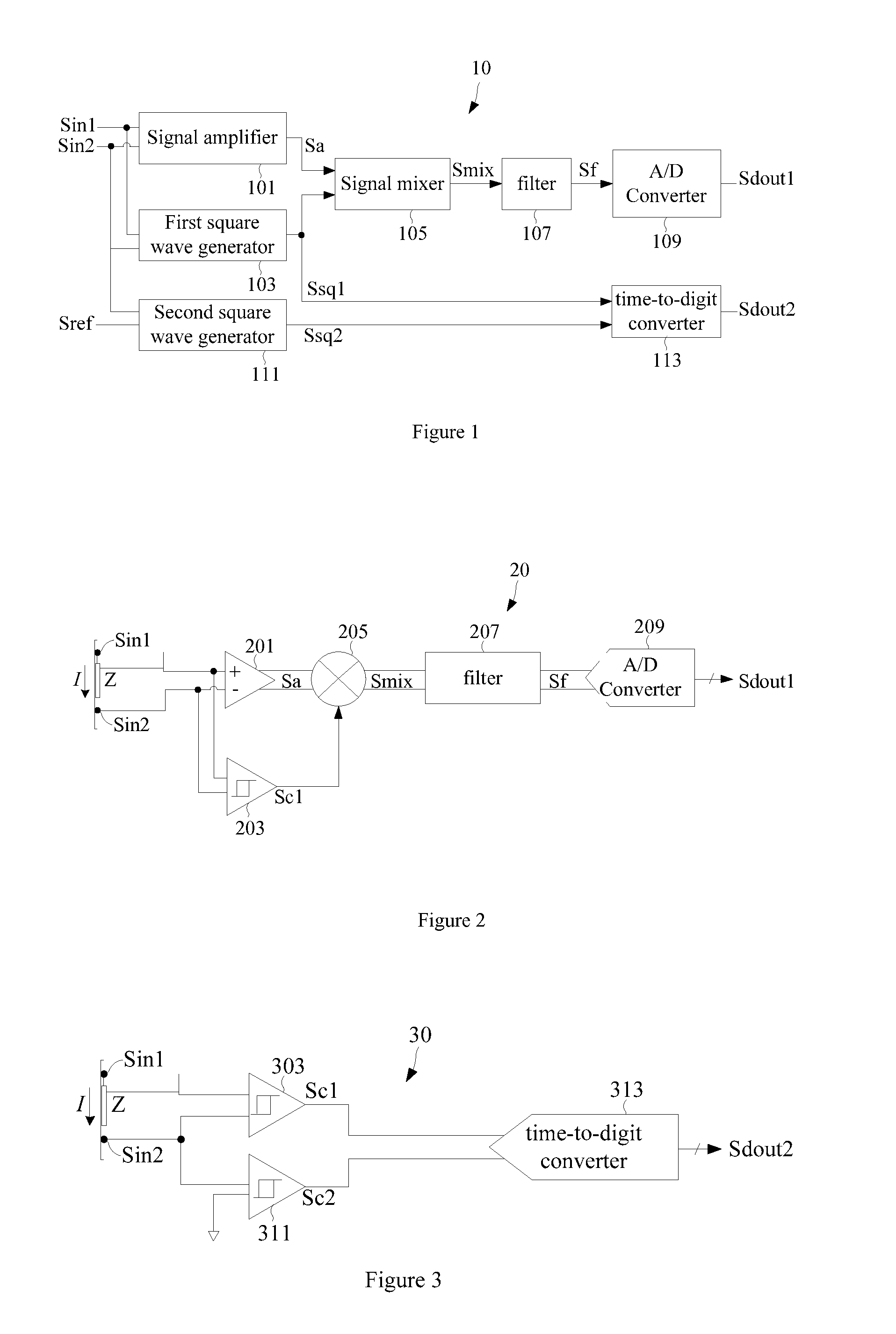
[0029]FIG. 1 shows a block diagram of one example according to a signal process system 10 of the invention. A corresponding signal process is performed for a sensory signal sensed by a sensor to further obtain ...


PUM

PropertyMeasurementUnit
signal strengthaaaaaaaaaa
frequencyaaaaaaaaaa
timeaaaaaaaaaa

Abstract

A signal process system and the method for the same and a biological resistance detection device and element used to perform corresponding signal process for sensory signal sensed by a sensor, wherein a minor AC electrical signal is injected into a biological tissue to be measured in order to sense the sensory signal of the biological tissue to be measured by means of the principle of Ohm's Law. Moreover, the sensory signal may be processed to restore a biological property of the measured biological tissue and to create an equivalent circuit parameter model representative of the biological property.

Description

CROSS-REFERENCE TO RELATED APPLICATIONS[0001]This application claims the priority of Republic of China Patent Application No. 103120260 filed on Jun. 11, 2014, in the State Intellectual Property Office of the R.O.C., the disclosure of which is incorporated herein by reference.BACKGROUND OF THE INVENTION[0002]1. Field of the Invention[0003]A signal process technology is related, particularly to a signal process system dividing a biological impedance information into two portions, gain and phase, for detection by using resistive property and capacitive property of a biological tissue to be measured, and the method for the same, and a biological impedance detection device and element.[0004]2. Descriptions of the Related Art[0005]Biological impedance technology is an important technology in clinical medicine and biomedicine fields for nature determination or quantification of characteristic behaviors of various biological tissues to observe differences of different biological tissues fr...

Claims


Application Information

Patent Timeline
Patent Type & Authority Applications(United States)
IPC IPC(8): G01N27/04A61B5/053
CPCA61B5/053G01N27/04A61B5/0537A61B5/7225
Inventor LEE, SHUENN-YUHTSAI, TSUNG-HAN
Owner NAT CHENG KUNG UNIV
Why Eureka
Try Eureka