Arbitrarily shaped deployable mesh reflectors

a mesh reflector and orbital shape technology, applied in the direction of antennas, electrical equipment, etc., can solve the problems of reducing the performance of the mesh reflector, reducing the degree of separation of the mesh, and limiting the size of the solid surface (or segmented surface) reflector, so as to control the magnitude of the tension in the chord

Active Publication Date: 2007-08-30
THE BOEING CO
View PDF16 Cites 42 Cited by
  • Summary
  • Abstract
  • Description
  • Claims
  • Application Information

AI Technical Summary

Benefits of technology

[0037] b. Provide a simple means to contro...

Problems solved by technology

So far, however, it has been limited to relatively small solid-surface (or segmented surface) reflectors due to limitations imposed by the fairing sizes of the launch vehicles on which they are flown.
One problem associated with the fabrication of such a mesh surface entails the ability to maintain the tension in the mesh within a certain desired range, and to terminate/cut the mesh edges in a manner that does not produce objectionable passive inter-modulation (PIM) or electro-static discharge (ESD), through the use of an appropriate mesh edge treatment.
“Pillowing” in a knitted wire mesh used as a radio-frequency reflective surface generally degrades performance, and increases the levels of the side lobes of radio-frequency energy reflected from the mesh.
The maximum net tension is limited by the available torque and force provided by the deployable reflector structure and by the desired deployment torque safety margin.
One disadvantage of the aforementioned methods is that they can be used with a gold-plated molybdenum mesh only in non-PIM sensitive applications.
The disadvantage of using ARACON™ fiber rather than Gold-plated Molybdenum is its increased insertion loss.
Disadvantages associated with other methods that utilize rigid or semi-rigid stri...

Method used


Image

  • Arbitrarily shaped deployable mesh reflectors
  • Arbitrarily shaped deployable mesh reflectors
  • Arbitrarily shaped deployable mesh reflectors

Examples


Embodiment Construction

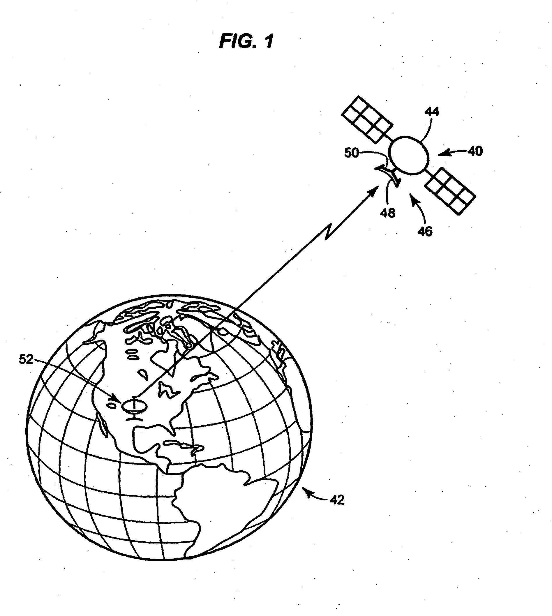
[0068] In FIG. 1, a perspective view of a satellite 40 in orbit about the earth 42 is illustrated. The satellite 40 itself includes both a body 44 and a deployable mesh reflector type antenna 46 mounted thereon. The deployable antenna 46, in turn, includes both a reflective mesh 48 and a supportive framework 50 for deploying and suspending the mesh 48. In having the deployable antenna 46 onboard, the satellite 40 is able to send and receive electromagnetic waves for thereby communicating with, for example, a ground communications station 52 while the satellite 40 is in orbit in outer space.

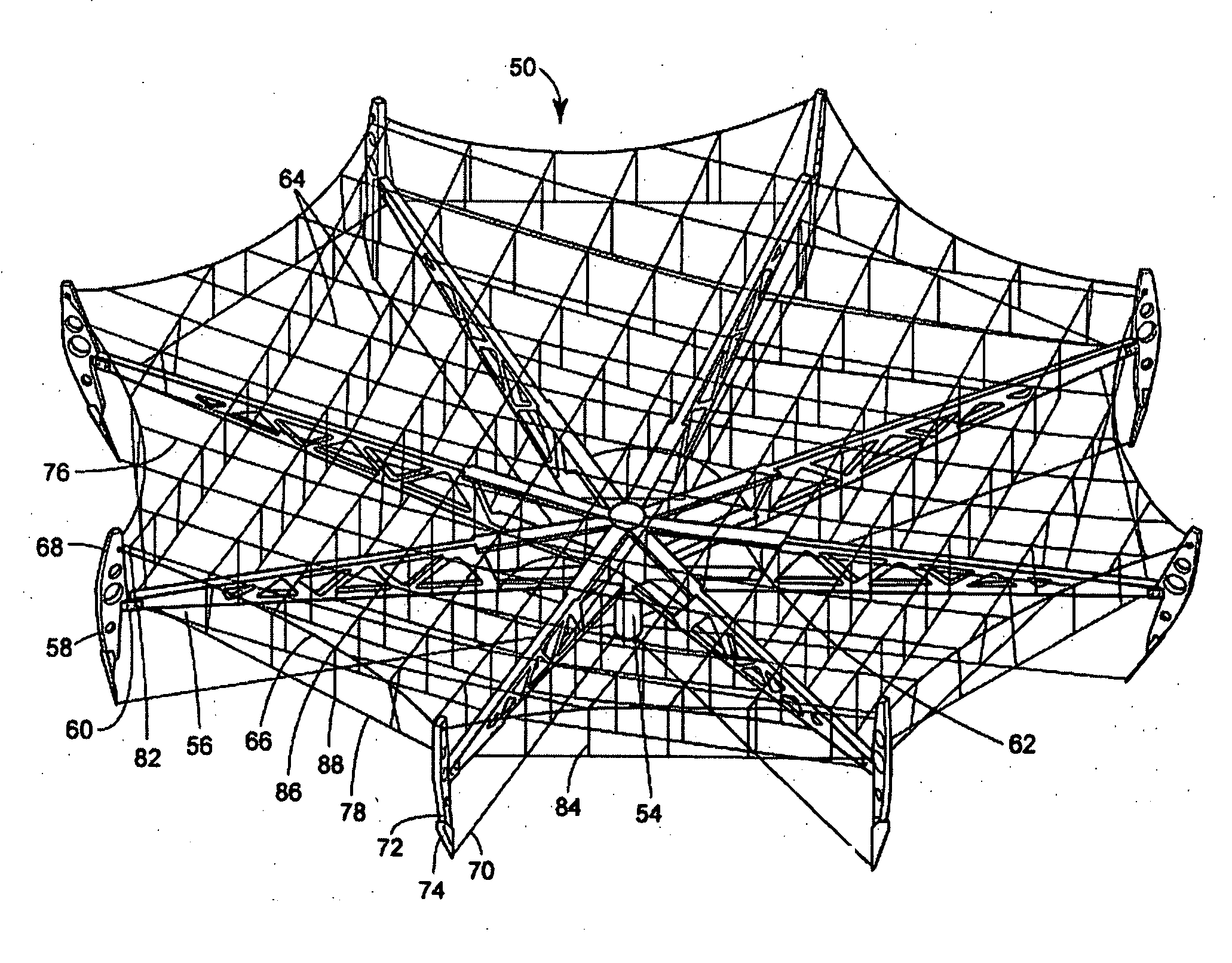
[0069] The reflector 46 is shown in FIG. 2 in a stowed configuration and in FIGS. 3 and 4 in a deployed configuration.

[0070] The reflector support structure comprises a slender composite hub 54 carrying eight radial ribs 56 with eight pivot arms 58, each mounted at a tip 60 of a rib 56. Each rib 56 may have a cross-section at the inner end having a substantially longer dimension in an axial dire...


PUM

PropertyMeasurementUnit
Angleaaaaaaaaaa
Angleaaaaaaaaaa
Angleaaaaaaaaaa

Abstract

A method and apparatus for making a mesh reflector that may be used to produce a shaped reflector is provided. The mesh reflector may be an umbrella-style deployable mesh reflector capable of approximating both parabolic and arbitrarily shaped reflecting surfaces, including those with regions of reversed curvature. The reflecting surface may be provided by a soft mesh attached to a highly pre-tensioned net composed of two sets of substantially parallel chords forming a plurality of parallelogram-shaped facets. The net/mesh may be made to conform to the desired shape by pulling and/or pushing on it at each of its facet corners via a set of finely adjustable tension ties and/or compression rods, the distal ends of which react against a set of pre-tensioned catenary-shaped chords disposed on the aft side of the mesh. The net/mesh and the aft catenaries may be supported and pretensioned by a set of substantially stiff radial ribs connected to a central hub by a means capable of providing high deployment torque and a means for controlling and coordinating the deployment of the ribs so that they reach their fully deployed positions nearly simultaneously. Methods for fabricating the mesh and attaching it to the net are also provided.

Description

[0001] This application is co-pending with an application of Samir Bassily entitled “Method and Apparatus for Grating Lobe Control in Faceted Mesh Reflectors,” commonly owned by the same assignee as this application, the entirety of which is hereby incorporated by reference herein. BACKGROUND [0002] 1. Field of the Disclosure [0003] The disclosure relates generally to mesh reflectors for antennas, and more particularly relates to mesh reflectors for antennas that may be used on spacecraft, and that are adapted to be stowed in a launch vehicle and subsequently deployed in outer space. [0004] 2. Background Description [0005] Over the past four decades, several styles of deployable mesh reflectors have been developed. The great majority of them were intended to approximate parabolic reflector surfaces, although any of them can theoretically be made to approximate other slowly varying surfaces, provided those surfaces do not have regions of negative curvature (i.e., are always curved to...

Claims


Application Information

Patent Timeline
IPC IPC(8): H01Q15/20
CPCH01Q15/161Y10T29/49904H01Q15/168
Inventor BASSILY, SAMIR F.
Owner THE BOEING CO
Why Eureka
Try Eureka