In situ determination of pixel mapping in interferometry

a technology of interferometry and in situ determination, applied in the field of interferometry, can solve the problems of zernike decomposition, wavefront generator, pixel coordinates, wavefront generators used for illuminating and imaging the part, and usually introduce a significant amount of distortion

Inactive Publication Date: 2007-08-30
ZYGO CORPORATION
View PDF3 Cites 16 Cited by
  • Summary
  • Abstract
  • Description
  • Claims
  • Application Information

AI Technical Summary

Benefits of technology

[0015] The present invention relates to interferometric methods and apparatus by which the map between pixel positions and corresponding part locations are determined in situ. The part under test, which is assumed to be a rigid body, is moved in one to six...

Problems solved by technology

Also for an exact numerical analysis of the figure errors of the part, it is often not admissible to leave the height results in pixel coordinates.
Wavefront generators and imaging optics used for illuminating and imaging the part usually introduce a significant amount of distortion.
For this, it is ...

Method used


Image

  • In situ determination of pixel mapping in interferometry
  • In situ determination of pixel mapping in interferometry
  • In situ determination of pixel mapping in interferometry

Examples


example a (

SPHERICAL CAVITY, Z-MOTION ONLY):

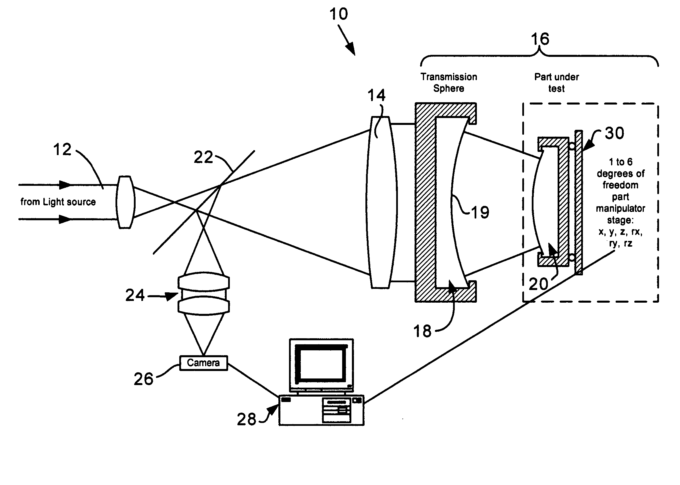
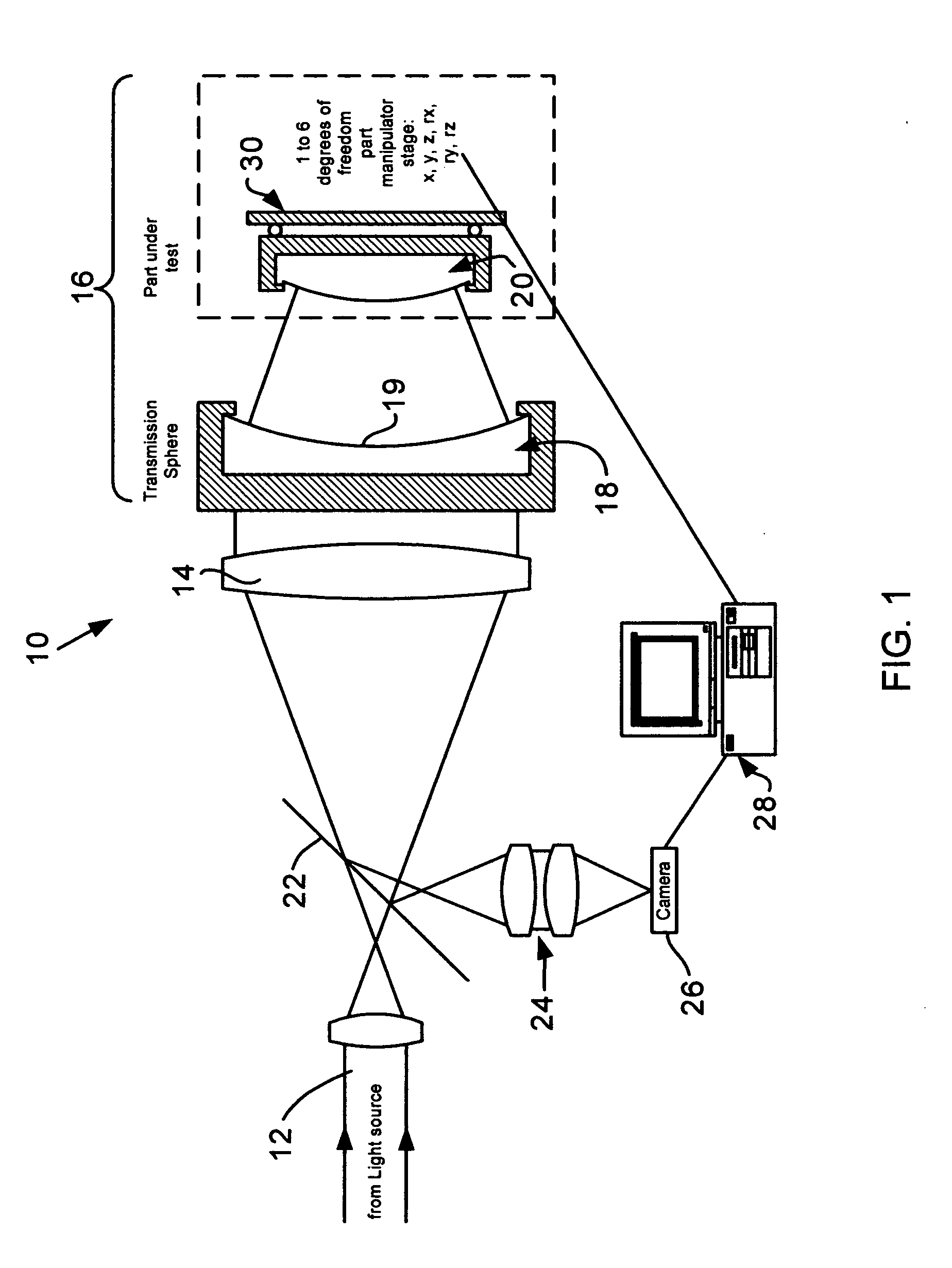
[0026] In principle, the method can be applied to many kinds of interferometers such as Fizeau-Interferometers, Mirau-Interferometers, Twyman-Green-Interferometers, Michelson-Interferometers, Linnik-Interferometers, Grazing incidence interferometers, Shearing interferometers, and so forth. In the following, a first version of the method is described using the special case of a Fizeau-interferometer. The Fizeau case is the easiest case because there are no additional optics between the reference and the object surface in a Fizeau configuration. Because of this, the Fizeau type is probably the most widely used interferometer in the optics industry.

[0027] In FIG. 1, a typical Fizeau setup is shown generally designated at 10. A beam 12 coming from a light source is expanded by a collimation system 14 and then illuminates a spherical Fizeau cavity 16. The light is partially reflected at the last surface 19 of element comprising a transmission sphere 18 (...

example b (

SPHERICAL CAVITY, x,y-MOTION ONLY):

[0039] Example A described the simplest case using an axial motion along only the system axis and described the basic idea of the method. It is obvious that measuring cos u and then calculating sin u is not a good measurement when u becomes small, that is, for pixels close to the optical axis. Here u only enters the equations quadratically. For a good measurement, a linear relationship would be preferable.

[0040] This is easily achieved by displacing the part laterally in two degrees of freedom, namely once along the x-axis using the displacement δx, and a second time using a y-displacement of δy.

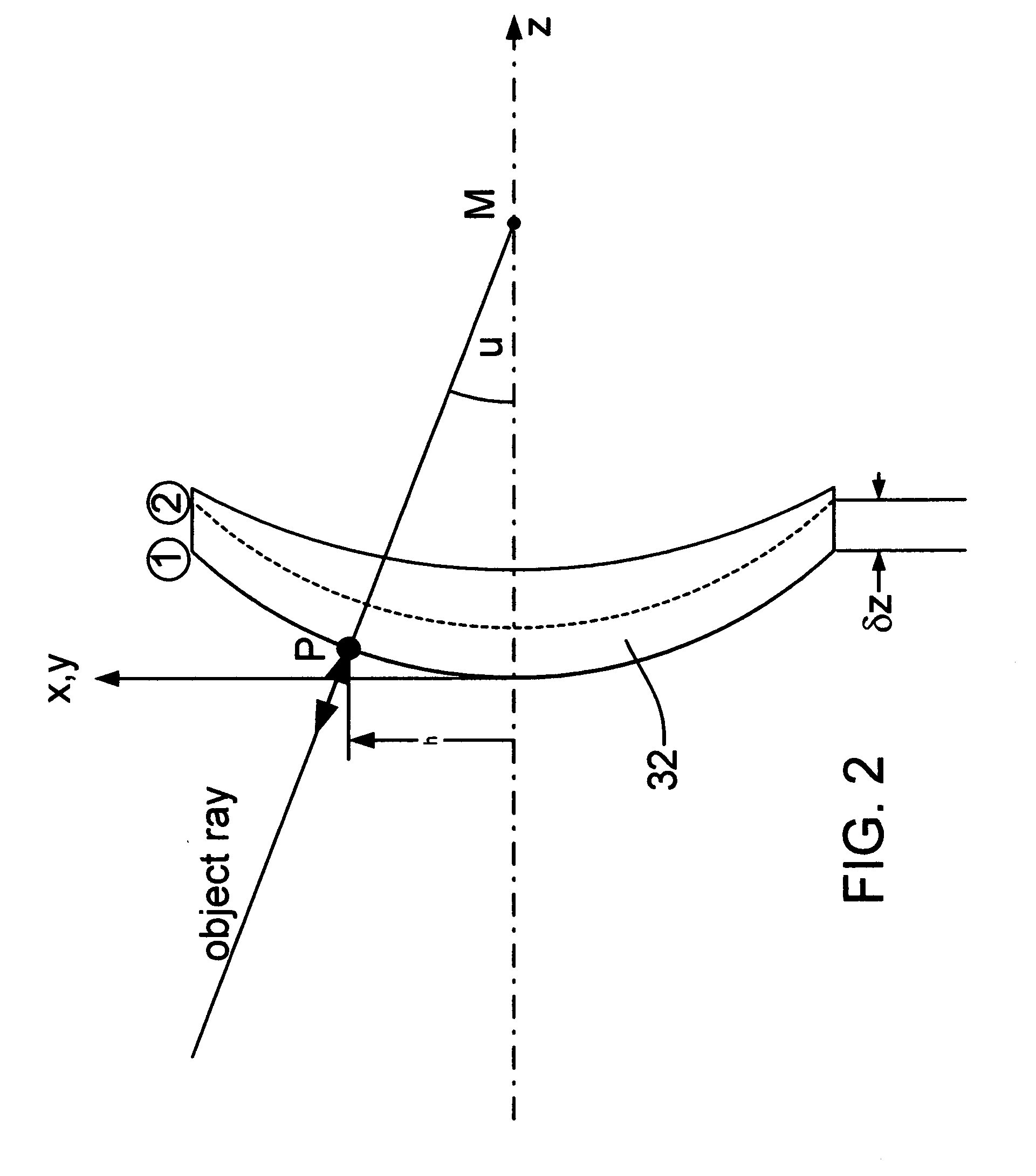
[0041] In this, the change in phase is with good approximation described as the scalar product between the probe motion (x or y, respectively) and the probe ray under consideration. Please refer again to FIG. 2. For the coordinates shown in the FIG. 2, this means that the phase difference with respect to the base position is given by:

DX=δ x sin u cos θ

DY...

example c (

SPHERICAL CAVITY, x,y,z-MOTION):

[0051] In principle, the approach described under Example B is sufficient to get the coordinates on a part if the manipulator commands (x,y)-motions precisely. In the following, a refinement of the method that is important for practical reasons is discussed.

[0052] Consider again a spherical cavity, but this time with a manipulator capable of manipulating the x, y, and z-degrees of freedom. Here, the following relationships hold:

DX=δ x sin u cos θ

DY=δ y sin u sin θ  (Eq. 7)

DZ=δ z cos u

[0053] The instrument measures the phase map differences DX, DY and DZ, and the manipulator reports back measured displacements δx, δy and δz. This is true in principle but, in practice, the manipulator cannot usually provide a pure x-shift, a pure y-shift or a pure z-shift with ultimate perfection. If a pure x-shift is commanded, for example, there may still be small motion components in the y- and z-direction as well.

[0054] Now consider the case where the external ...


PUM


Abstract

Interferometric methods and apparatus by which the map between pixel positions and corresponding part locations are determined in situ. The part under test, which is assumed to be a rigid body, is precisely moved from a base position to at least one other position in one to six degrees of freedom in three-dimensional space. Then, the actual displacements are obtained. The base position is defined as the position with the smallest fringe density. Measurements for the base and all subsequent positions are stored. After having collected at least one measurement for each degree of freedom under consideration, the part coordinates are calculated using the differences of the various phase maps with respect to the base position. The part coordinates are then correlated with the pixel coordinates and stored.

Description

FIELD OF THE INVENTION [0001] In general, this invention relates to the field of interferometry and, in particular, to methods and apparatus for in situ determination of the mapping of pixels in a detector array on to their corresponding locations of the surface of a part to be measured. BACKGROUND OF THE INVENTION [0002] In the field of high precision sphere and asphere measurements, contemporary phase evaluation techniques yield surface error maps with sub-nm uncertainties. The measurand in these cases is the height deviation between the part under test and the ideal geometry measured along the surface normal. [0003] The result of such measurements is usually delivered as a two-dimensional height map sampled on a regular grid. Initially, an interferometer gives the result in pixel coordinates of the acquisition camera. For visually assessing the quality of the surface under test, it is possible to leave the result in pixel coordinates and this is very often done. However, if the r...

Claims


Application Information

Patent Timeline
IPC IPC(8): G01B11/02
CPCG01B11/2441
Inventor DRESEL, THOMAS
Owner ZYGO CORPORATION
Why Eureka
Try Eureka