
Image forming method and image forming apparatus

Inactive Publication Date: 2007-08-30
FUJIFILM BUSINESS INNOVATION CORP
View PDF18 Cites 21 Cited by
  • Summary
  • Abstract
  • Description
  • Claims
  • Application Information

AI Technical Summary

Benefits of technology

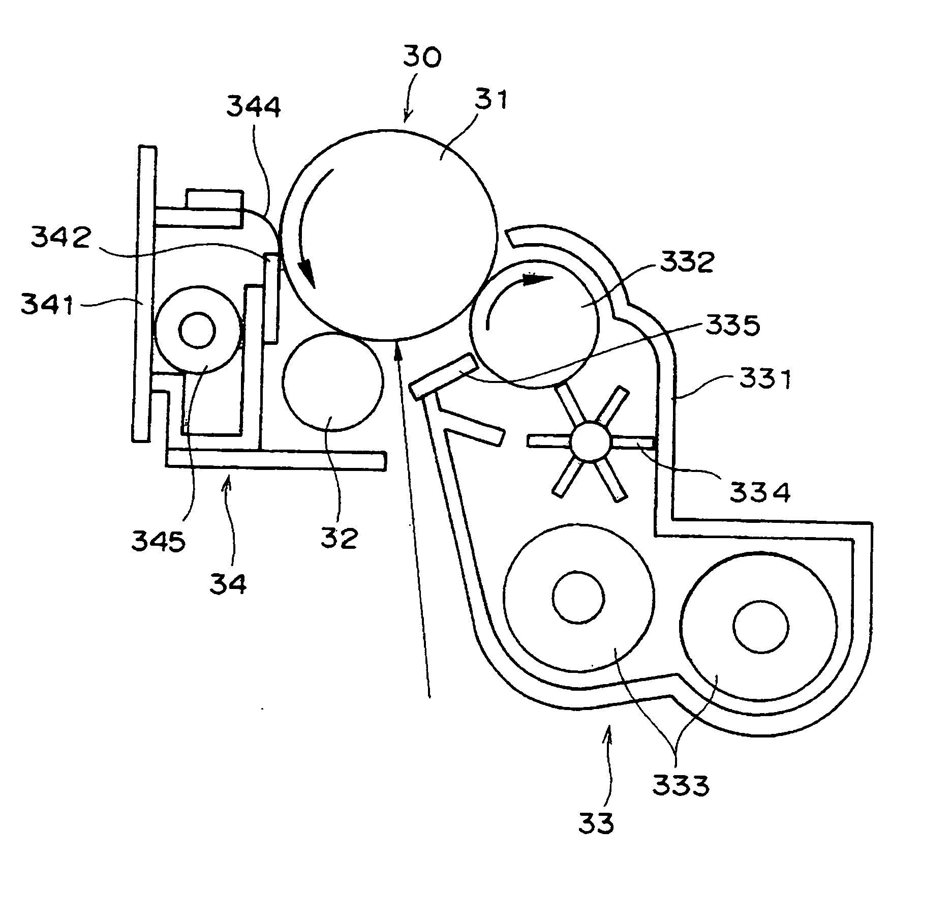
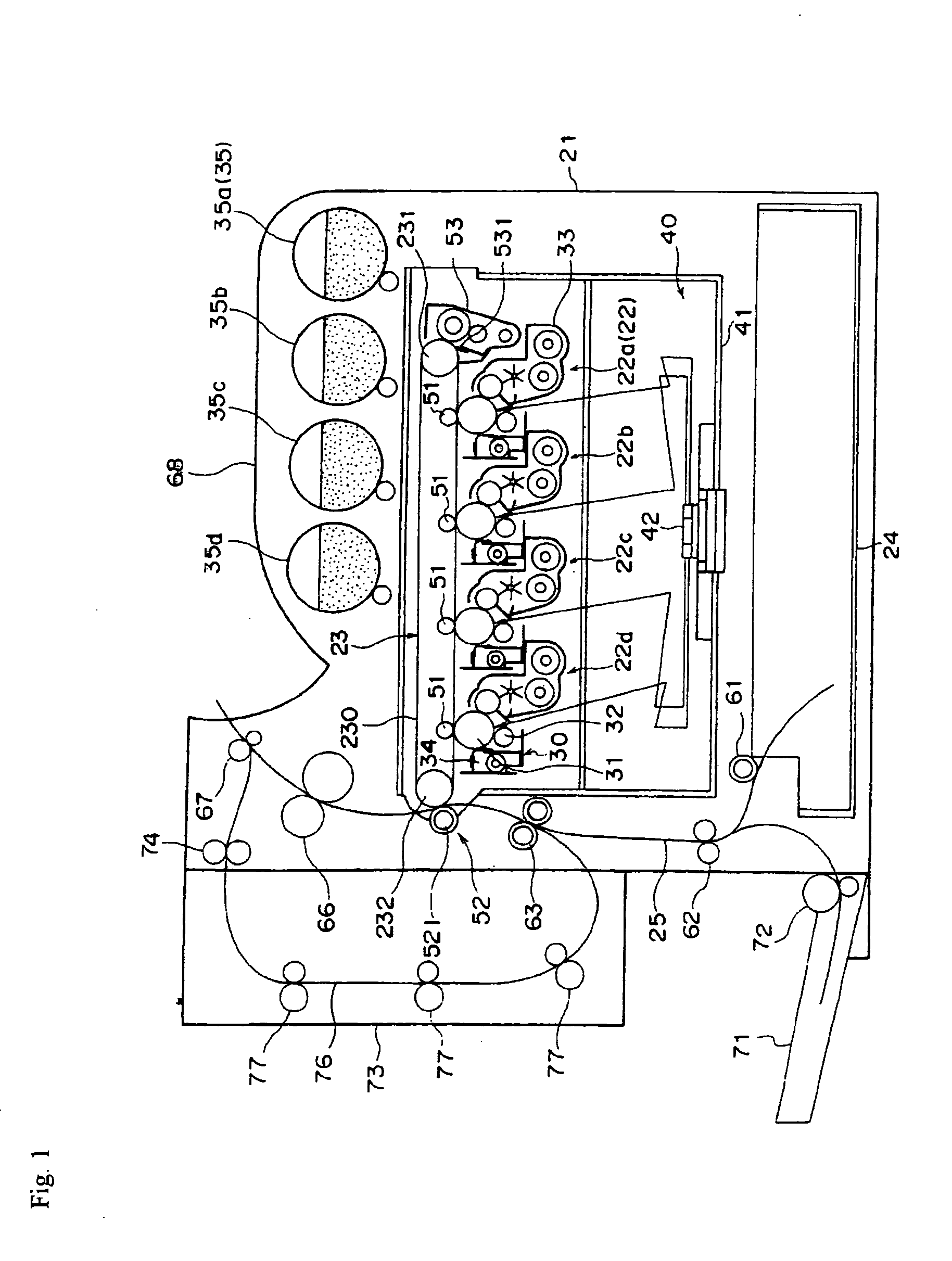
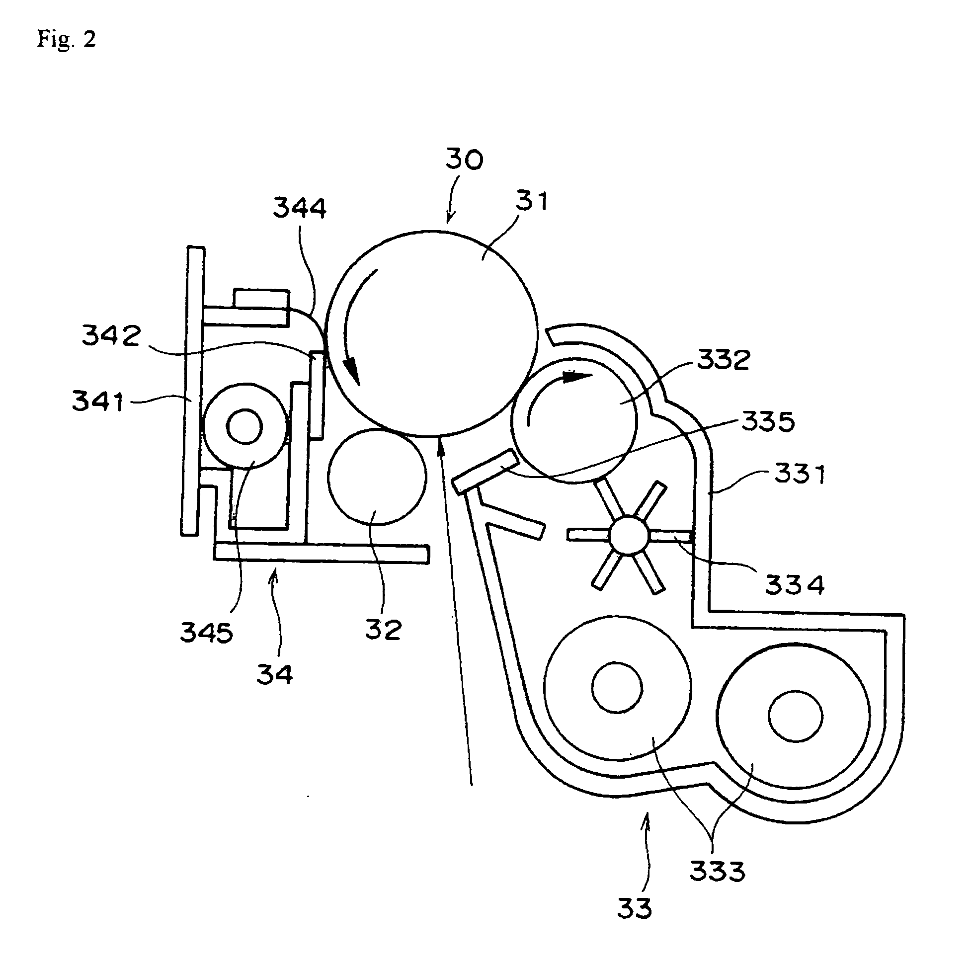
[0035]The image forming apparatus according to an aspect of the invention may comprise a process cartridge that is attachable to and separable from the body of the image forming apparatus and includes at least the image carrier and the cleaning blade.
[0035]The image forming apparatus according to an aspect of the invention may comprise a process cartridge that is attachable to and separable from the body of the image forming apparatus and includes at least the image carrier and the cleaning blade.

Problems solved by technology

Accordingly, maintenance cost has been a large burden from the viewpoint of users.
Furthermore, in particular, when the image carrier is hard to abrade, a discharge product generated by discharge from a charging unit that imparts electric charge onto the surface of an image carrier makes the image deletion easily occur under a high humidity environment.
Accordingly, suppression of the image deletion is an important issue in a long-lasting image forming apparatus and process cartridge, in which an image carrier and a cleaning blade both excellent in wear resistance are combined.

Method used


Image

  • Image forming method and image forming apparatus
  • Image forming method and image forming apparatus
  • Image forming method and image forming apparatus

Examples


examples

[0264]Hereinafter, the invention will be described by reference to Examples. However, the Examples should not be construed as limiting the invention. In the following description, the term “part” refers to “part by mass”.

—Production of Cleaning Blade—

[0265]At first, a hard segment material composed of polycaprolactone polyol (PLACCEL 205, with an average molecular weight of 529 and a hydroxyl value of 212 mgKOH / g, manufactured by Daicel Chemical Industries, Ltd.) and polycaprolactone polyol (PLACCEL 240, with an average molecular weight of 4,155 and a hydroxyl value of 27 mgKOH / g, manufactured by Daicel Chemical Industries, Ltd.), which are polyol components, and a soft segment material made of an acrylic resin containing two or more hydroxyl group (ACTFLOW UMB-2005B, manufactured by Soken Chemical Engineering Co., Ltd.) are mixed in the ratio of 8:2 (by mass).

[0266]Next, 6.26 parts by mass of 4,4′-diphenylmethane diisocyanate (MILLIONATE MT, hereinafter referred to as MDI, manufact...


PUM


Abstract

An image forming method in which an image carrier that has a surface layer containing a resin having a crosslinking structure is used; a material of a portion of the cleaning blade which portion contacts the surface of the image carrier satisfies 3.92≦M≦29.42, 0≦α≦0.294, and S≦250; an absolute value of difference in circumferential velocity between the image carrier and the intermediate transfer member is larger than zero; a polishing agent is present at a contact portion between the image carrier and the intermediate transfer member; M represents 100% modulus; a represents a ratio of a change in stress (Δ stress) to a change in a strain amount (Δ strain amount) from 100% strain to 200% strain in a stress-strain curve; and S represents a breaking elongation measured according to JIS K6251 using a dumbbell type #3 test piece.

Description

BACKGROUND[0001]1. Technical Field[0002]The present invention relates to an image forming method that can be utilized in a copy machine and the like that forms an image electrophotographically and an image forming apparatus using the same.[0003]2. Related Art[0004]In an image forming apparatus that uses an electrophotography method, periodical maintenance has been necessary. Accordingly, maintenance cost has been a large burden from the viewpoint of users. Furthermore, from the viewpoint of eco-friendliness, the image forming apparatus and a process cartridge are desired to have a longer life.[0005]In order to realize a long-lasting image forming apparatus and a process cartridge, it is necessary to improve the rate-determining factor of wearing type service life; e.g., (1) making an image carrier hard to abrade, and making the surface of the image carrier slippy, (2) reducing damage on the image carrier by a blade, and simultaneously (3) the blade itself is hard to abrade.[0006]Fur...

Claims


Application Information

Patent Timeline
IPC IPC(8): G03G21/00
CPCG03G21/0017
Inventor TESHIGAWARA, TORU
Owner FUJIFILM BUSINESS INNOVATION CORP
Learn More