
Endoscopic passage confluent structure

a confluent structure and endoscope technology, applied in the field of endoscope passage confluent structure, can solve the problems of considerable difference between the fluids flowing through the two flow passages, conspicuous pressure loss, and possibly contaminated viewing windows, and achieve the effect of reducing resistan

Inactive Publication Date: 2007-09-06
FUJI PHOTO OPTICAL CO LTD
View PDF6 Cites 34 Cited by
  • Summary
  • Abstract
  • Description
  • Claims
  • Application Information

AI Technical Summary

Benefits of technology

[0010]The present invention has been made in view of the foregoing points, and it is an object thereof to provide an endoscopic flow-passage confluent structure small and compact in size but highly strong so that smooth flow can be formed with reduced resistance through any of the flow passages that are joined together.

Problems solved by technology

During endoscopic examination, the viewing window is possibly contaminated with body fluids, etc.
However, the flow passage joined to the straight flow passage is bent sharply in its route and hence considerably great in the resistance to flow, thus resulting in a conspicuous pressure loss with a turbulent flow at the confluent point.
Therefore, a considerable great difference encounters between the fluids flowing through the two flow passages.
Thus, the connection is possibly broken or cracked by the reaction of such an external force.
Because of a cleaning liquid used as a cleaning fluid, the liquid if leaks through the broken point would cause a contamination in the interior of the body control portion.
However, because such a block structure requires a greater size as compared to the branch structure, there is a difficulty in obtaining a sufficient space for arrangement in the body control portion.
Besides, there is a fear that the block urges the received members, such as light guides and cables, provided in a manner passing through the body control portion, into a disconnection.

Method used


Image

  • Endoscopic passage confluent structure
  • Endoscopic passage confluent structure
  • Endoscopic passage confluent structure

Examples


Embodiment Construction

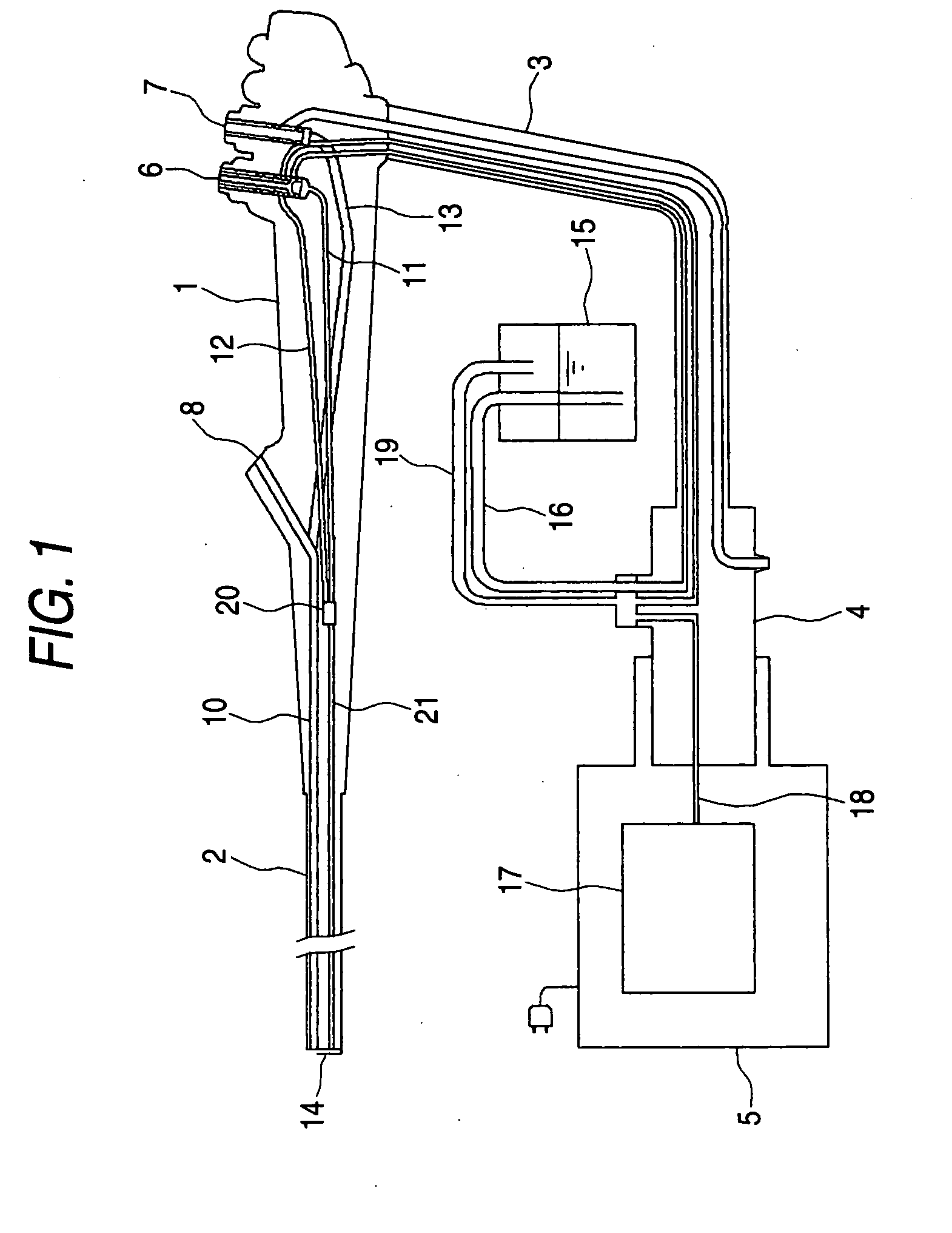
[0022]Based on the drawings, explanation will now made on an embodiment according to the present invention. FIG. 1 shows a schematic arrangement of conduits provided in an endoscope. In the figure, reference numeral 1 designates a body control portion, 2 an insertion portion to a body cavity, etc., and 3 a universal cord. The universal cord 3 is provided with a connector 4 at the tip thereof. The connector 4 is removably connected to a control unit 5 (generally, including a light source and a video-signal processing circuit). The body control portion 1 is arranged with a gas / water feed valve 6 and a suction valve 7, and also with a manipulation-tool guide 8.

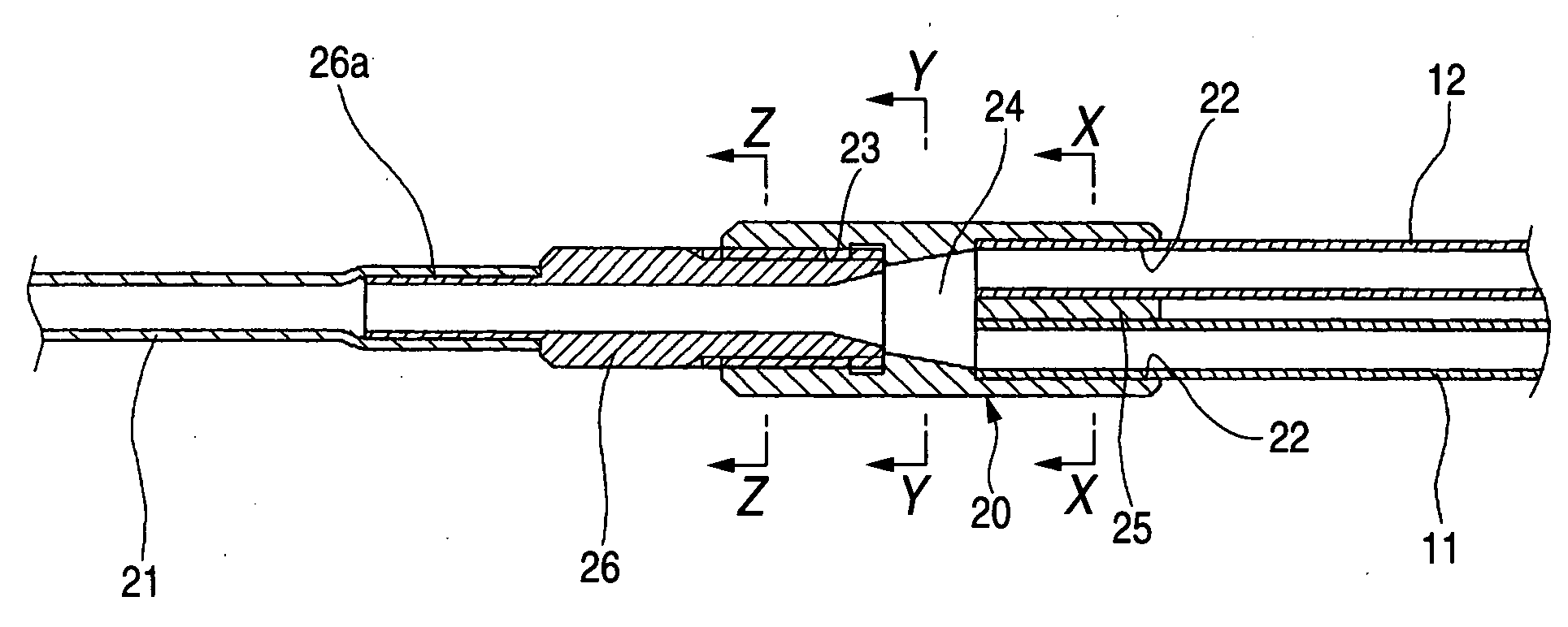
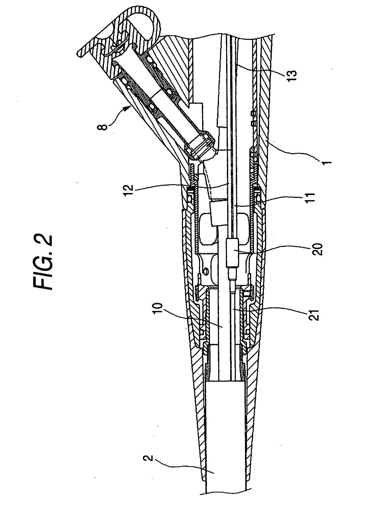
[0023]The endoscope includes mainly conduits including a manipulation-tool receiving channel 10, a gas-feed tube 11, a liquid-feed tube 12 and a suction passage 13. The manipulation-tool receiving channel 10 has a base communicating with the manipulation-tool guide 8 and a tip opening in a tip face of the insertion portion 2. The...


PUM


Abstract

An endoscopic flow-passage confluent structure that connects a gas-feed tube and a liquid-feed tube provided in an endoscope to a confluent tube communicating with an ejection nozzle arranged at a tip of an insertion portion of the endoscope and for ejecting a cleaning fluid toward a viewing window of the endoscope, the structure comprising: (i) a passage connection member having one end opened with two upstream-passage receiving bores in which the gas-feed and liquid-feed tubes are respectively inserted and fixed, other end opened with one downstream-passage receiving bore, and an intermediate region that communicates the upstream-passage receiving bores with downstream-passage receiving bore and comprises a passage confluent space having a diameter increasing in a taper-form in a direction of from the downstream-passage receiving bore toward the upstream-passage receiving bores; and (ii) a coupler pipe having one end connected to the downstream-passage receiving bore and other end connected with a base of the confluent tube.

Description

BACKGROUND OF THE INVENTION[0001]1. Field of the Invention[0002]The present invention relates to an endoscopic passage-confluent structure that joins a liquid feed tube and a gas feed tube together into connection to a confluent tube communicating with an ejection nozzle, in a cleaning mechanism arranged in an endoscope and for feeding a cleaning fluid, of a liquid or a gas, to a viewing window arranged at the tip of an insertion portion thereof.[0003]2. Description of the Related Art[0004]The endoscope, particularly for medical use, is provided with a viewing window at the tip of its insertion portion in order to observe the body interior. During endoscopic examination, the viewing window is possibly contaminated with body fluids, etc. For this reason, a cleaning mechanism is provided for the viewing window. The cleaning mechanism is constructed with an ejection nozzle arranged nearby the viewing window, a feed passage of a cleaning fluid, e.g. a cleaning liquid or a pressurized ga...

Claims


Application Information

Patent Timeline
Patent Type & Authority Applications(United States)
IPC IPC(8): B08B3/00
CPCA61B1/00091A61B19/34A61B1/126A61B1/125A61B90/70A61B1/015A61B1/00
Inventor TORII, YUICHI
Owner FUJI PHOTO OPTICAL CO LTD
Features
  • Generate Ideas
  • Intellectual Property
  • Life Sciences
  • Materials
  • Tech Scout
  • Unparalleled Data Quality
  • Higher Quality Content
  • 60% Fewer Hallucinations
Learn More