Method and apparatus for dissipating heat

a technology for dissipating apparatus and heat, applied in the direction of electrical apparatus construction details, lighting and heating apparatus, laminated elements, etc., can solve the problem of increasing heat generation of components, and achieve the effect of limited heat load and difficult fabrication

Inactive Publication Date: 2007-09-06
SENSIS CORPORATION
View PDF18 Cites 15 Cited by
  • Summary
  • Abstract
  • Description
  • Claims
  • Application Information

AI Technical Summary

Benefits of technology

[0009] The present invention provides thermally enhanced packages for high heat density electronic components which allow for extracting heat from extremely localized areas, effectively spreading this heat over a larger area, thereby decreasing its density, and efficiently transferring the heat to the equipment's cooling media. The package preferably incorporates a unique combination of high thermal conductivity and thermal-expansion matched materials. The high thermal conductivity of the materials (when provided) promotes heat conduction away from the components. The matched thermal expansion of the materials, to that of the components (when provided), minimizes the occurrences of the stresses in the components with temperature excursions.
[0022] A thermally enhanced package design according to the present invention preferably employs all solid-type materials, i.e., no internal fluids. There is no fundamental factor which limits either the heat loads or temperature ranges at which it functions. Preferably, the package design is compact and self-contained. The package design lends itself to production of electronic assemblies by being producible, and consequently affordable, using developed manufacturing processes. By contrast, alternative approaches for thermally enhancing electronic packaging have typically limited heat load and temperature ranges, are typically bulky and complex, and / or difficult to fabricate, rendering them costly.
[0023] The thermally enhanced packages according to the present invention enable insertion of new electronic component technologies into commercial and military systems with application to computers, transportation, communications, sensors, opto-electronics, and industrial controls. With this component packaging, systems using air-based cooling can be extended to higher power levels, deferring the need to transition to liquid coolant. For the highest power systems, the thermally enhanced packaging may also be advantageously employed with a liquid coolant media.

Problems solved by technology

As a consequence, these components are generating increasingly larger amounts of heat in smaller areas.
Removal of this heat has been identified as perhaps the biggest issue facing computer designers.

Method used


Image

  • Method and apparatus for dissipating heat
  • Method and apparatus for dissipating heat
  • Method and apparatus for dissipating heat

Examples


first embodiment

[0098] a heat dissipation device according to the present invention is depicted in FIGS. 1-3.

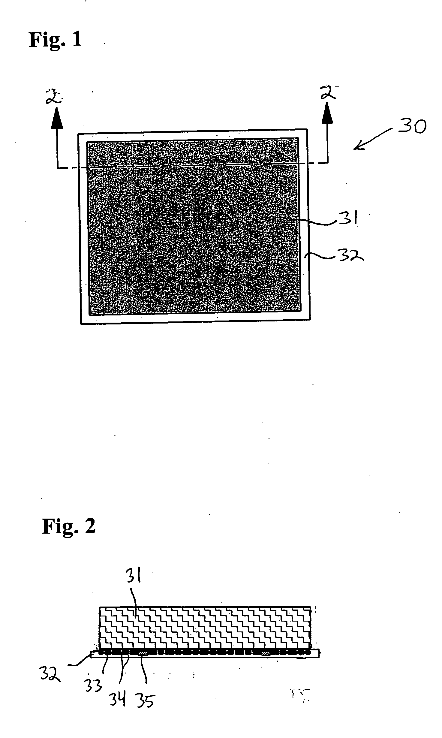
[0099]FIG. 1 is a front view of the heat dissipation device 30 according to the first embodiment. The heat dissipation device 30 includes a porous foam heat exchange component 31 positioned on a base 32. The porous foam heat exchange component 31 is formed of carbon foam or metallized foam (e.g., carbon or aluminum).

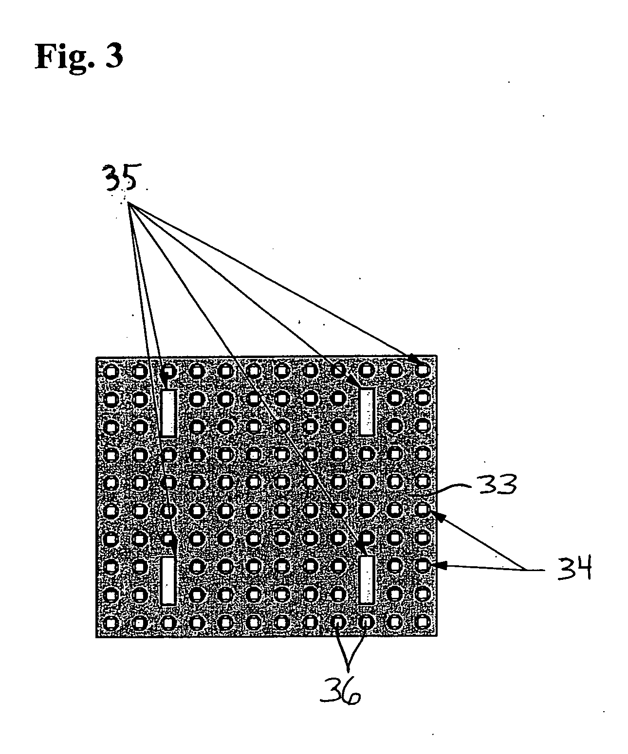
[0100]FIG. 2 is a cross-sectional view of the heat dissipation device 12 shown in FIG. 1 taken along line 2-2 in FIG. 1. FIG. 2 shows the base 32 of the heat dissipation device 30, as well as a base element 33 positioned within the base 32. A plurality of base element vias 34 are formed in the base element 33. In addition, a plurality of heat transfer pieces 35 are positioned in the base element 33.

[0101]FIG. 3 is a front view of the base element 33 in the heat dissipation device 30. FIG. 3 shows the base element 33 and a plurality of base element vias 34 formed in the base ele...

second embodiment

[0102] a heat dissipation device according to the present invention is depicted in FIGS. 4-6.

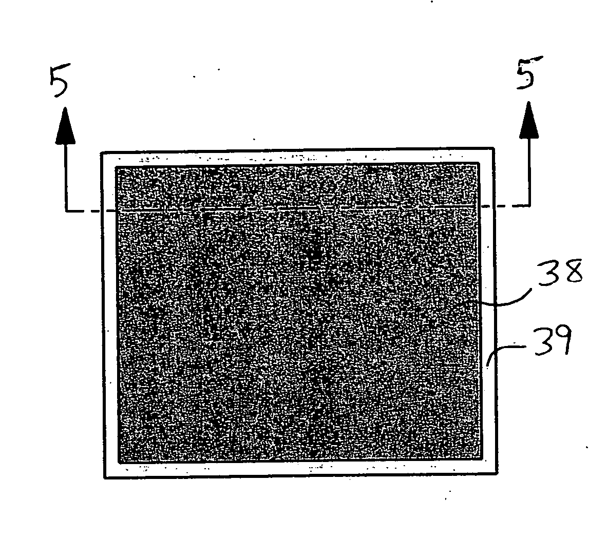
[0103]FIG. 4 is a front view of the heat dissipation device 37 according to the second embodiment. The heat dissipation device 37 includes a porous foam heat exchange component 38 positioned on a base 39. The porous foam heat exchange component 38 is formed of carbon foam or metallized foam (e.g., carbon or aluminum).

[0104]FIG. 5 is a cross-sectional view of the heat dissipation device 37 shown in FIG. 4 taken along line 5-5 in FIG. 4. FIG. 5 shows the base 39 of the heat dissipation device 37, as well as a base element 42 positioned within the base 39. A plurality of base element vias 43 are formed in the base element 42, and cylindrical slivers 44 are positioned in each of the base element vias 43.

[0105]FIG. 6 is a front view of the base element 42 in the heat dissipation device 37. FIG. 6 shows the base element 42, the base element vias 43 and the cylindrical slivers 44. The base 39 is ...

third embodiment

[0106] a heat dissipation device according to the present invention is depicted in FIG. 7.

[0107]FIG. 7 is a side view of the heat dissipation device 45, which includes a plurality of fiber plate heat exchange components 46 stacked as a laminate and positioned on a base 47. The fiber plate heat exchange components 46 comprise carbon fiber plates.


PUM

PropertyMeasurementUnit
angleaaaaaaaaaa
angleaaaaaaaaaa
angleaaaaaaaaaa

Abstract

A heat dissipation device, comprises a base, a base element positioned within the base, and at least one heat exchange component mounted on the base. The at least one heat exchange component comprises at least one porous foam component (e.g., a metallized foam or a carbon foam), at least one fiber plate (e.g., comprising carbon fibers) and / or at least one corrugated metal element (e.g., comprising aluminum or copper). The device can further comprise at least one sliver (e.g., comprising diamond or carbon fiber). The device can further comprise at least one heat transfer piece (e.g., of diamond) positioned within the base. There is also provided a method of dissipating heat, comprising passing fluid, e.g., air, across at least one heat exchange component of such a device.

Description

FIELD OF THE INVENTION [0001] The present invention relates to apparatus for dissipating heat. The present invention further relates to the thermal management of electronic components, and more particularly, limiting temperatures of components generating heat at very high density. The present invention further relates to methods of dissipating heat, e.g., from electronic components. [0002] In preferred aspects, the present invention relates to apparatus for dissipating heat from electronic components, e.g., electronic components for a radar antenna. BACKGROUND OF THE INVENTION [0003] Evolving electronic components are operating at higher speeds and higher power levels and are being packed more and more densely. As a consequence, these components are generating increasingly larger amounts of heat in smaller areas. To limit the temperatures of these components, and thereby realize peak performance plus reliable operation, this heat energy must be effectively removed. [0004] The contin...

Claims


Application Information

Patent Timeline
Patent Type & Authority Applications(United States)
IPC IPC(8): H05K7/20
CPCH01L23/373H01L23/3733H01L23/3736H01L2924/3011H01L2924/0002H01L2924/00F28F3/022F28F13/003
Inventor EDWARD, BRIAN J.RUZICKA, PETER J.SABATINO, MARK
Owner SENSIS CORPORATION
Why Eureka
Try Eureka