Chip Component Carrying Method and System, and Visual Inspection Method and System

a technology of carrying method and component, applied in the direction of conveyor parts, transportation and packaging, instruments, etc., can solve the problems of incorrect workpiece attitude, inability to earn throughput, and inability to stabilize the attitude of workpieces, so as to improve the delivery of workpieces, stabilize the delivery operation, and carry workpieces stably

Inactive Publication Date: 2007-09-06
TDK CORPARATION
View PDF6 Cites 26 Cited by
  • Summary
  • Abstract
  • Description
  • Claims
  • Application Information

AI Technical Summary

Benefits of technology

[0047] The present invention makes it possible to realize a chip-component carrying method and system for stably carrying a workpiece while stabilizing the attitude by first and second rotary discs, stabilizing the delivery operation according to improvement of the workpiece delivery between rotary discs, and accelerating and stabilizing a series of workpiece carryings by first and second rotary discs.
[0048] Furthermore, by using the chip-component carrying method and carrying system, it is possible to realize a chip-component visual inspection method and system capable of improving the number of inspections, decreasing the inspection cost, and improving the inspection accuracy and yield. Particularly, the method and system are effective to improve and stabilize the inspection accuracy in the visual inspection of four sides of very small chip components (1005, 0603, 0402 and so on).

Problems solved by technology

The following are problems of a conventional carrying technique.
(1) In the case of a workpiece carrying method, the attitude of a workpiece is not stabilized due to the influence of acceleration or deceleration when carrying the workpiece by intermittent driving.
Moreover, there is a problem that a throughput cannot be earned.
(2) When carrying a workpiece by continuous rotary discs, because the workpiece is carried by the dead weight of the workpiece, an incorrect workpiece attitude occurs by the influence of a shift of the workpiece due to centrifugal force caused by rise of a carrying speed or mechanical vibration due to a change of equipment to high speed.
When the state of a detection face is fluctuated due to the incorrect attitude of the workpiece, a trouble occurs in visual inspection accuracy (recognition accuracy).
(3) When carrying a workpiece by belts, similarly there is a problem that an attitude of the workpiece is fluctuated due to a vibration of the belt itself.
Moreover, the following are problems of a conventional inspection method.
(1) In the case of a detection method of four sides of a workpiece using a transparent member, though a carrying method is simple because no workpiece is delivered, dirt and scratch easily occur on the transparent member and these dirt and scratch cause a problem in an inspection accuracy and there is a problem in stable detection (originally nondefective product is confused as defective product).
In the case of this method, however, there are problems that the gap between the workpiece and the upper rotary disc 52 is influenced by the dimensional tolerance of the thickness of the workpiece, clearance control is difficult, and delivery of the workpiece is not well-performed when the gap is too large.
Moreover, there is a problem that a trouble that a workpiece having an incorrect workpiece attitude is caught in the gap between the upper and lower rotary discs easily occurs.
In this case, three or four component members are necessary and there is a problem that a structure becomes complicated.

Method used


Image

  • Chip Component Carrying Method and System, and Visual Inspection Method and System
  • Chip Component Carrying Method and System, and Visual Inspection Method and System
  • Chip Component Carrying Method and System, and Visual Inspection Method and System

Examples


embodiment 1

[0096] According to this embodiment 1, it is possible to obtain the following advantages.

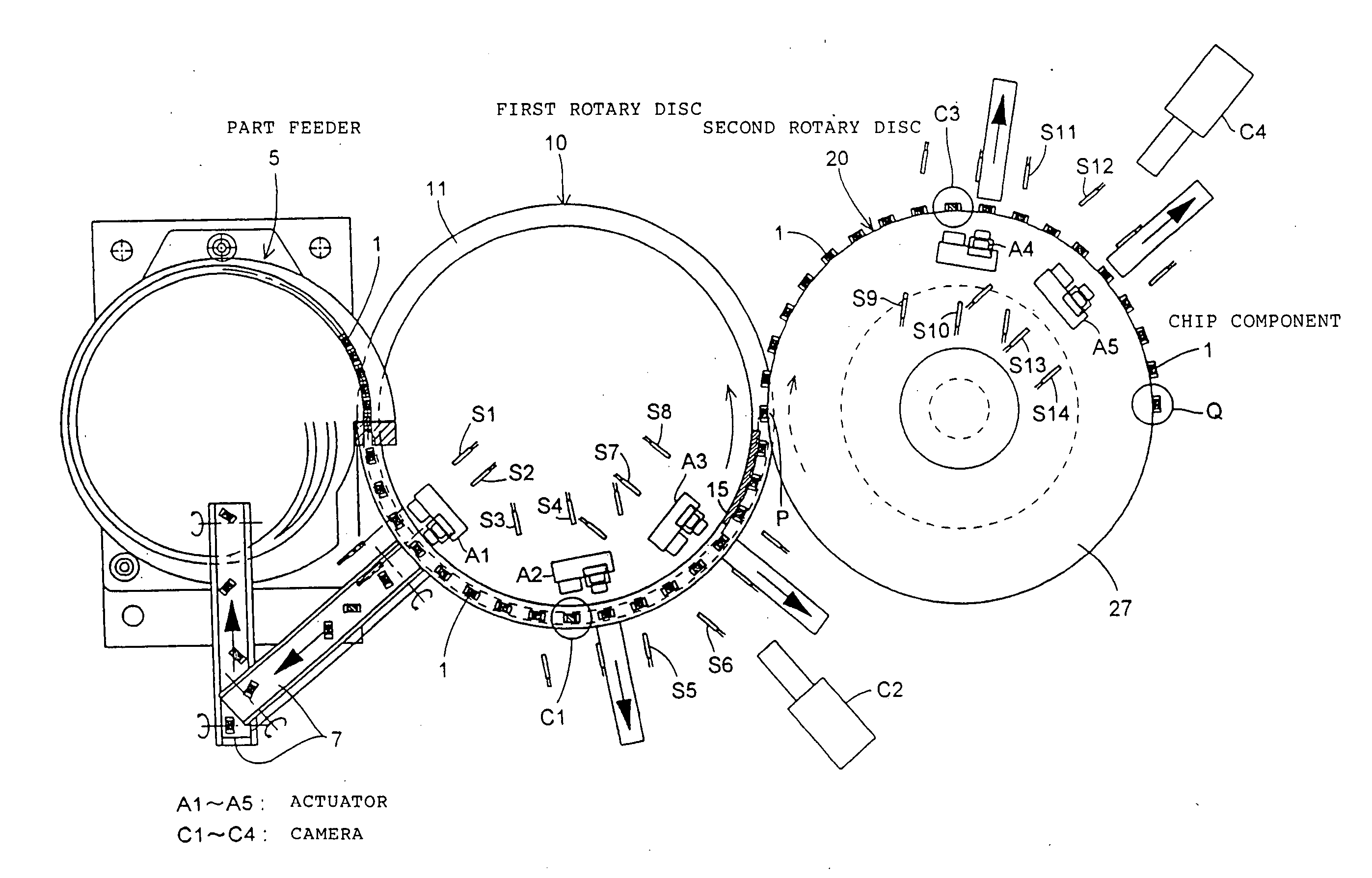
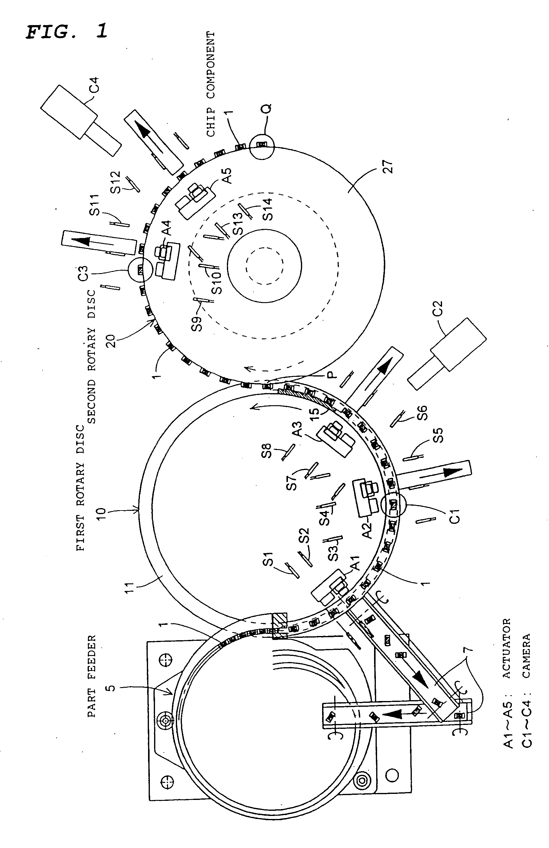
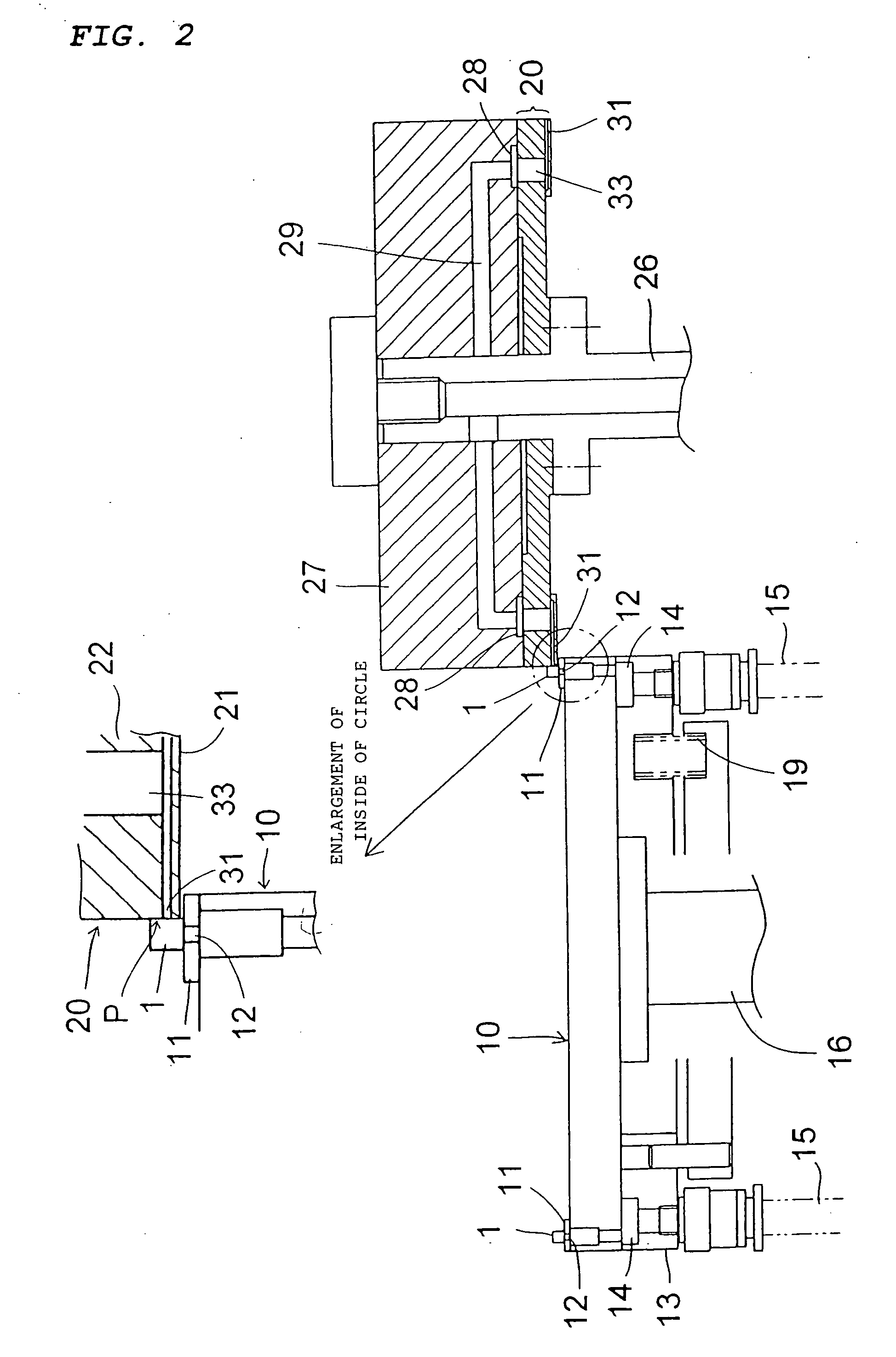
[0097] (1) Because a configuration is used in which the chip component 1 serving as a workpiece is sucked and held on a horizontal plane of the first rotary disc 10 and carried and then sucked and held on the vertical plane of the second rotary disc 20 and carried, chip components can be transferred from the first rotary disc 10 to the second rotary disc 20 independently of the fluctuation of the thickness of a chip component, and the chip-component delivery operation is securely performed. A trouble due to the fluctuation of the thicknesses of chip components or breakage of a chip component which occurs in a conventional example as shown in FIGS. 6 and 7 does not occur. Moreover, it is possible to transfer a chip component without changing the attitude of the chip component (without vertically or horizontally reversing the attitude) and stably carry the chip component.

[0098] (2) By continuousl...

embodiment 2

[0102] Embodiment 2 of the present invention is described by referring to FIG. 9 to FIGS. 15A and 15B. In these drawings, the first rotary disc 10 and second rotary disc 20 constitute the carrying system of a rectangular-parallelepiped chip component serving as a workpiece and a configuration in which the chip components 1 are successively supplied to the chip located plane (upside) 11 on the outer margin of the first rotary disc 10 from the part feeder 5 is the same as the case of the embodiment 1.

[0103] In this case, when supplying a chip component from the part feeder 5 to the first rotary disc 10, the chute portion of the part feeder 5 is set to the upside of the chip located plane 11 of the first rotary disc 10 as shown in FIG. 10. However, a small gap is necessary so that the first rotary disc 10 does not interfere with the chute portion of the part feeder 5. Moreover, when delivering the chip component 1 to the first rotary disc 10, it is necessary to minimize the distance D ...

embodiment 3

[0116]FIG. 16 shows embodiment 3 of the present invention, in which the arrangement of a camera serving as imaging means for performing visual inspection is changed. In this case, first camera C1, second camera C2 and fourth camera C4 serving as imaging means are arranged by facing the carrying route of the chip component 1 of the first rotary disc 10 and third camera C3 is set by facing the carrying route of the chip component 1 of the second rotary disc 20. The first camera C1 corresponding to the carrying route of the first rotary disc 10 images and inspects (image processing inspection) the upside of the chip component 1, second camera C2 images and inspects one lateral of the chip component 1, fourth camera C4 images and inspects the other lateral of the chip component 1, and third camera C3 corresponding to the carrying route of the second rotary disc 20 images and inspects the downside of the chip component 1, which are CCD cameras or line sensors. In this case, a chip compon...


PUM

PropertyMeasurementUnit
lengthaaaaaaaaaa
widthaaaaaaaaaa
widthaaaaaaaaaa

Abstract

A method and a system for stabilizing the sight line of a chip component being carried on two discs, for stabilizing delivery of the chip component between the two discs, and improving and stabilizing the inspection accuracy in the visual check of the chip component. This is achieved by employing a mechanism for carrying the chip component while supporting it on the horizontal plane of the first rotary disc and then carrying the chip component while suction-holding it on the vertical plane of the second rotary disc. When the chip component is carried on the first rotary disc, the upper surface and one side face of the chip component are imaged by first and second cameras. When the chip component is carried on the second rotary disc, the lower surface and the other side face of the chip component are imaged by third and fourth cameras.

Description

TECHNICAL FIELD [0001] The present invention relates to a chip-component carrying method and system suitable to image four faces (upper face, lower face, and both side faces other than both end faces) of a chip component such as a chip condenser or chip inductor and a visual inspection method and system using the carrying method and system. BACKGROUND ART [0002] The following are carrying techniques for transferring a chip component such as a chip condenser or chip inductor for inspection. [0003] (1) Technique for forming a workpiece housing groove on a rotary disc, supplying a workpiece (object to be carried) to the workpiece housing groove, and separation-carrying the workpiece in accordance with an intermittent action (commercial inspection machine) [0004] (2) Technique for separation-supplying a workpiece to a continuously-rotating rotary disc from a part feeder as disclosed in Japanese Patent Laid-Open No. 2000-266521 or Japanese Patent Publication No. H6-87072 and then carryin...

Claims


Application Information

Patent Timeline
Patent Type & Authority Applications(United States)
IPC IPC(8): B65G29/00B65G47/86G01N21/95G01N21/956G01R31/01
CPCG01N21/8803G01R31/013G01N21/95B65G17/323B65G47/911B65G2203/041
Inventor KOBAYASHI, MASAYOSHIMIZUNO, TORU
Owner TDK CORPARATION
Why Eureka
Try Eureka