
Water control valve

a technology of water control valves and valve bodies, applied in the direction of filtration separation, bends, separation processes, etc., can solve the problems of media being ineffective at softening, media may be disrupted, and the effect of scaling problems

Active Publication Date: 2007-09-06
CORNELL BOYD
View PDF17 Cites 19 Cited by
  • Summary
  • Abstract
  • Description
  • Claims
  • Application Information

AI Technical Summary

Benefits of technology

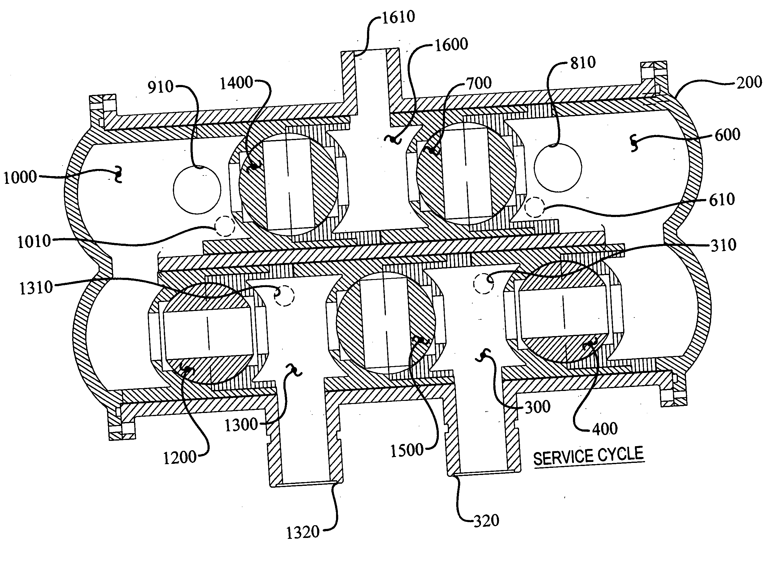
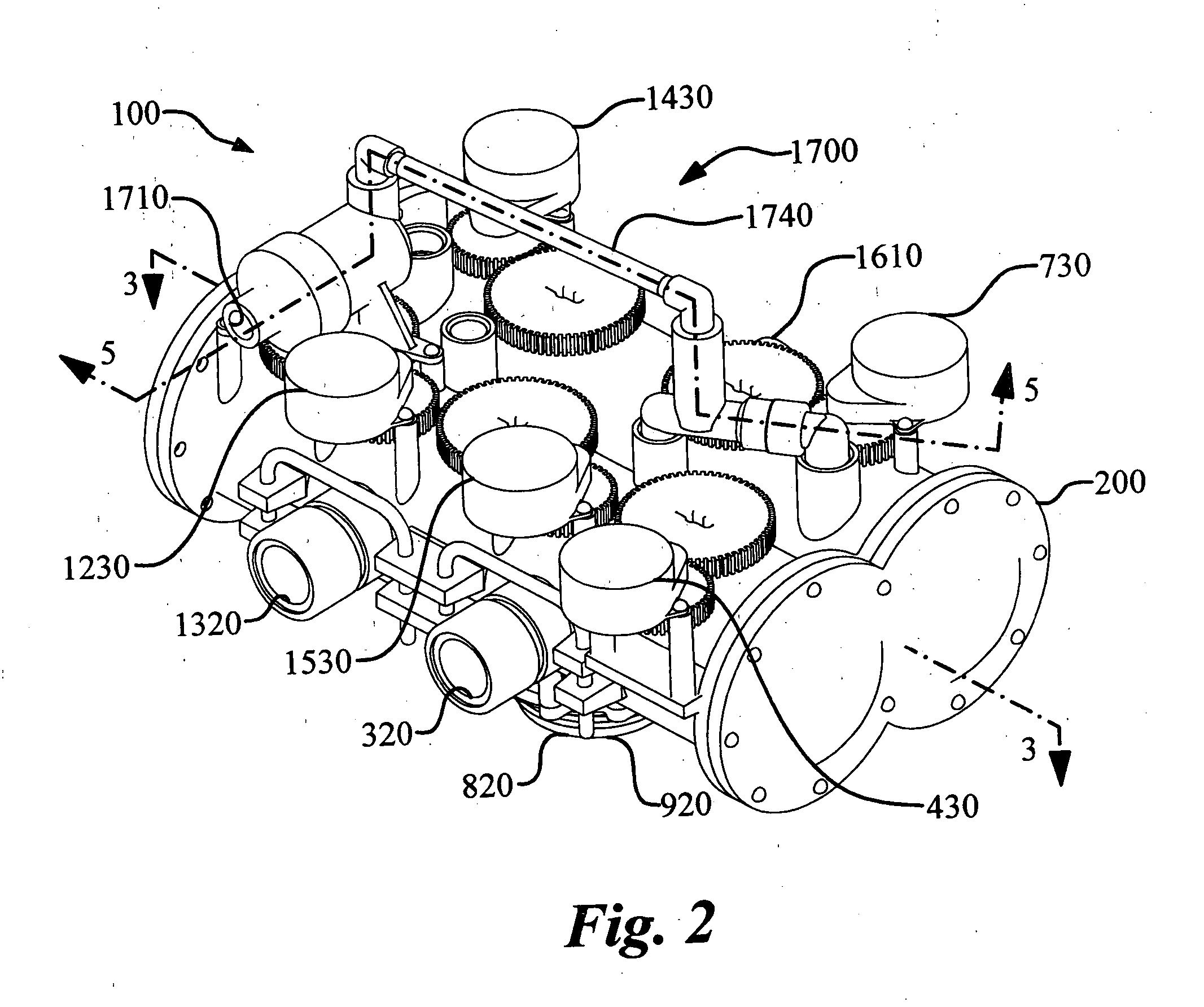
[0015] The perimeter passageway has a backwash port and a perimeter port. The backwash port is in fluid communication with the backwash chamber and the perimeter port provides fluid communication with the treatment tank. Similarly, the central passageway has a fast rinse port and a central port. The fast rinse port is in fluid communication with the fast rinse chamber and the central port is in fluid communication with the treatment tank. The central port resides within and is concentric to the perimeter port. Each of the valves has an open position and a closed position thereby providing control and routing of the water flow inside the housing.
[0017] In the down regeneration configuration, the regeneration connector is in fluid communication with the influent chamber having an influent routing port and the backwash chamber having a backwash injection port. The regeneration injection assembly is connected to the housing at the influent routing port and the backwash injection port. The regeneration connection port is in fluid communication with the regeneration agent reservoir, the regeneration valve is in fluid communication with the regeneration connection port and the regeneration passageway, and the regeneration passageway is in fluid communication with the regeneration connector. When the regeneration valve is open, the regenerating agent may flow from the regeneration agent reservoir through the regeneration passageway to the regeneration connector, and when the regeneration valve is closed, the regenerating agent is substantially prevented from flowing from the regeneration agent reservoir through the regeneration passageway to the regeneration connector. The regeneration connector contains a regeneration agent injector.
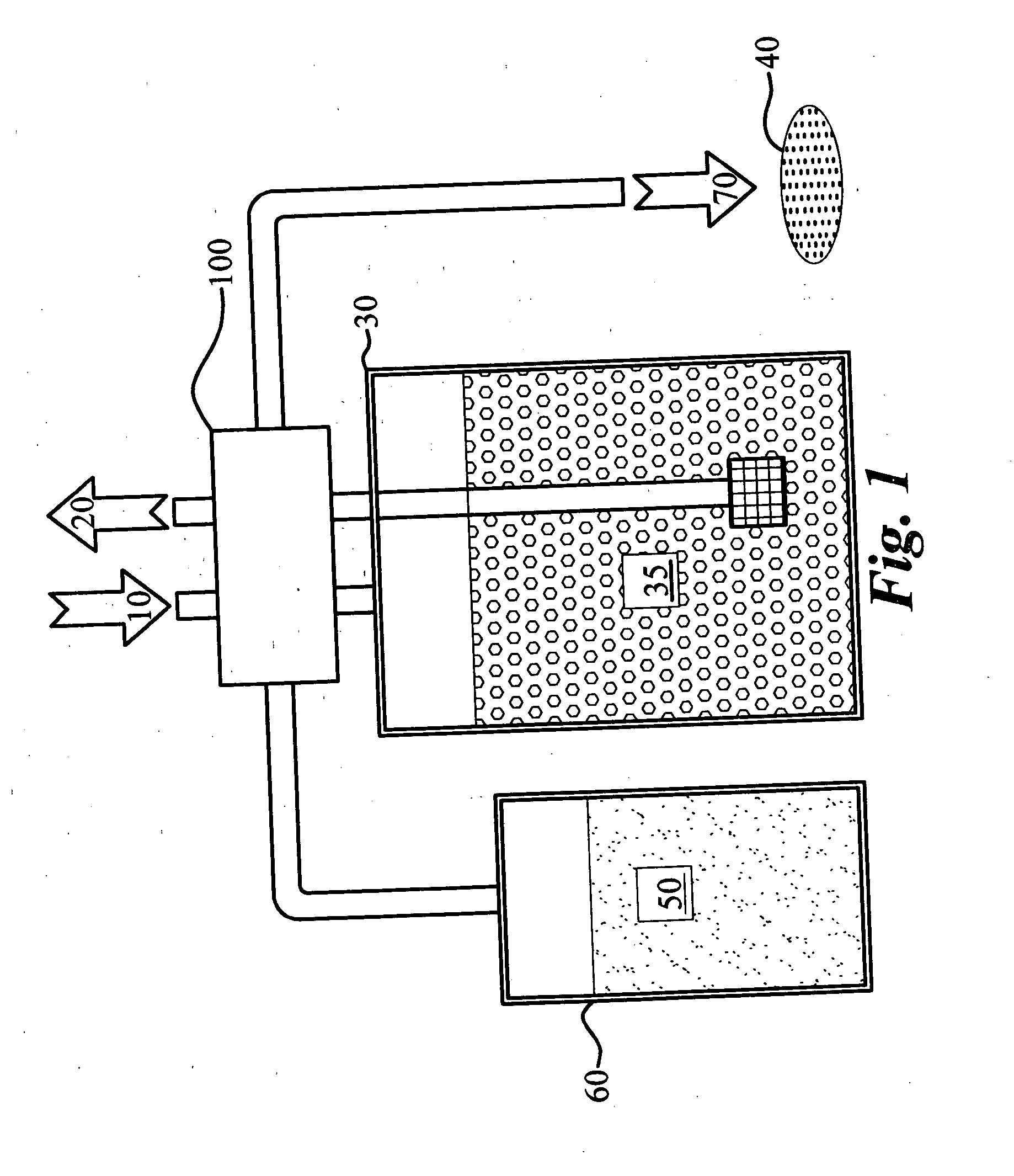
[0020] During the operation of the water control valve, the valves are positioned to direct water flow into five defined cycles, namely: a service cycle, a backwash cycle, a fast rinse cycle, and a down regeneration cycle and a down regeneration refill cycle or an up regeneration cycle and an up regeneration refill cycle. Each cycle is characterized by a unique set of valve positions. The purpose of the service cycle is to treat water for use. The purpose of the backwash cycle is to reverse the flow of water through the media relative to the service cycle. The reversed water flow helps flush away any macroscopic contaminates that are trapped in the media. In the fast rinse cycle the water control valve directs water through the media in the same direction as the service cycle to clean and repack the media. In general, the up and down regeneration cycles transfer the regeneration agent from the regeneration agent reservoir to the media. After repeated regeneration cycles, the regeneration reservoir will be emptied of the regeneration agent. The water control valve is designed to direct water flow to the regeneration reservoir to refill it with water during the down or up regeneration refill cycle.

Problems solved by technology

Since these compounds can become insoluble in water, particularly at elevated temperatures, they can precipitate and create scaling problems by adhering to piping and other surfaces.
The scale can cause problems by restricting flow through pipes and may appear as a residue in bathroom showers, dishwashers, and in other areas of the home.
Eventually, the media becomes ineffective at softening.
Following the backwashing cycle the media may be disrupted.
If the media does not settle back into position properly the treatment process may be negatively impacted.
In fact, past water control valve designs prohibit variable sequence or cycle independency.
Additionally, there remains an unfilled need to provide a valve that may be configured quickly and easily in the field to operate in an up regeneration or down regeneration configuration.

Method used


Image

  • Water control valve
  • Water control valve
  • Water control valve

Examples


Embodiment Construction

[0045] The water control valve (100) of the instant invention enables a significant advance in the state of the art. The preferred embodiments of the device accomplish this by new and novel arrangements of elements and methods that are configured in unique and novel ways and which demonstrate previously unavailable but preferred and desirable capabilities. The detailed description set forth below in connection with the drawings is intended merely as a description of the presently preferred embodiments of the invention, and is not intended to represent the only form in which the present invention may be constructed or utilized. The description sets forth the designs, functions, means, and methods of implementing the invention in connection with the illustrated embodiments. It is to be understood, however, that the same or equivalent functions and features may be accomplished by different embodiments that are also intended to be encompassed within the spirit and scope of the invention...


PUM

PropertyMeasurementUnit
sizeaaaaaaaaaa
sizeaaaaaaaaaa
sizeaaaaaaaaaa

Abstract

A water control valve designed to control the flow of water from a source to a treatment tank having a plurality of treatment media, thereby providing a supply of treated water, and also provides other cycle controls. For instance, the water control valve directs water to backwash the media of sediment for discharge to a drain, permits regeneration of the media by directing a regeneration agent through the media, directs water through the media in a fast rinse cycle, and directs water to a regeneration agent reservoir for the purpose of refilling the reservoir. The water control valve has six valves and five motors for controlling the valve positions. The valves are fluidly connected to six chambers providing a pathway for water flow between the valves, to a regeneration injection assembly, through a central passageway or a perimeter passageway, to the treatment tank.

Description

TECHNICAL FIELD [0001] The instant invention relates to water control valves for directing the flow of water in a water treatment system, and, more particularly, to a water control valve having a housing enclosing five valves and an injection assembly having a sixth valve such that the valves are rotatably connected to five motors, wherein the valve mates with a water softening tank. BACKGROUND OF THE INVENTION [0002] Water treatment systems are designed to condition incoming water in some fashion. A variety of water conditioning processes are available. For instance, water conditioning can be a distillation process, a demineralization process, a reverse osmosis process, or a filtration process, to name only a few. The demineralization process is of particular interest. [0003] The demineralization process removes dissolved compounds, for example, calcium and magnesium compounds, from water. Since these compounds can become insoluble in water, particularly at elevated temperatures, t...

Claims


Application Information

Patent Timeline
Patent Type & Authority Applications(United States)
IPC IPC(8): C02F1/42C02F5/00
CPCC02F1/42C02F2209/005F16K11/10C02F2303/16C02F2303/14Y10T137/4486Y10T137/86558
Inventor CARNELL, BOYD
Owner CORNELL BOYD
Learn More