Discharge Container

Inactive Publication Date: 2007-09-06
THE PROCTER & GAMBLE COMPANY +1
View PDF5 Cites 80 Cited by
  • Summary
  • Abstract
  • Description
  • Claims
  • Application Information

AI Technical Summary

Benefits of technology

[0032] The invention having the above structure offers the following advantages. In the aspect of the invention according to Claim 1, in particular, the edge of the rotatable partitioning plate is formed by the spatula-shaped sliding member made of soft material. Thus, the sliding member can slide along the shape of the inner surface of the container body with slight resistance while more securely retaining the tightness of sealing. Accordingly, an appropriate amount of discharge can be easily and securely obtained by smooth rotational operation. Also, the contents can be completely scraped from the inner surface of the container body without leaving the contents inside the container, and t

Problems solved by technology

However, it sometimes occurs that too much amount of the contents is taken out and the surplus contents are returned to the container, which is unhygienic.
Also, since

Method used


Image

  • Discharge Container
  • Discharge Container
  • Discharge Container

Examples


first embodiment

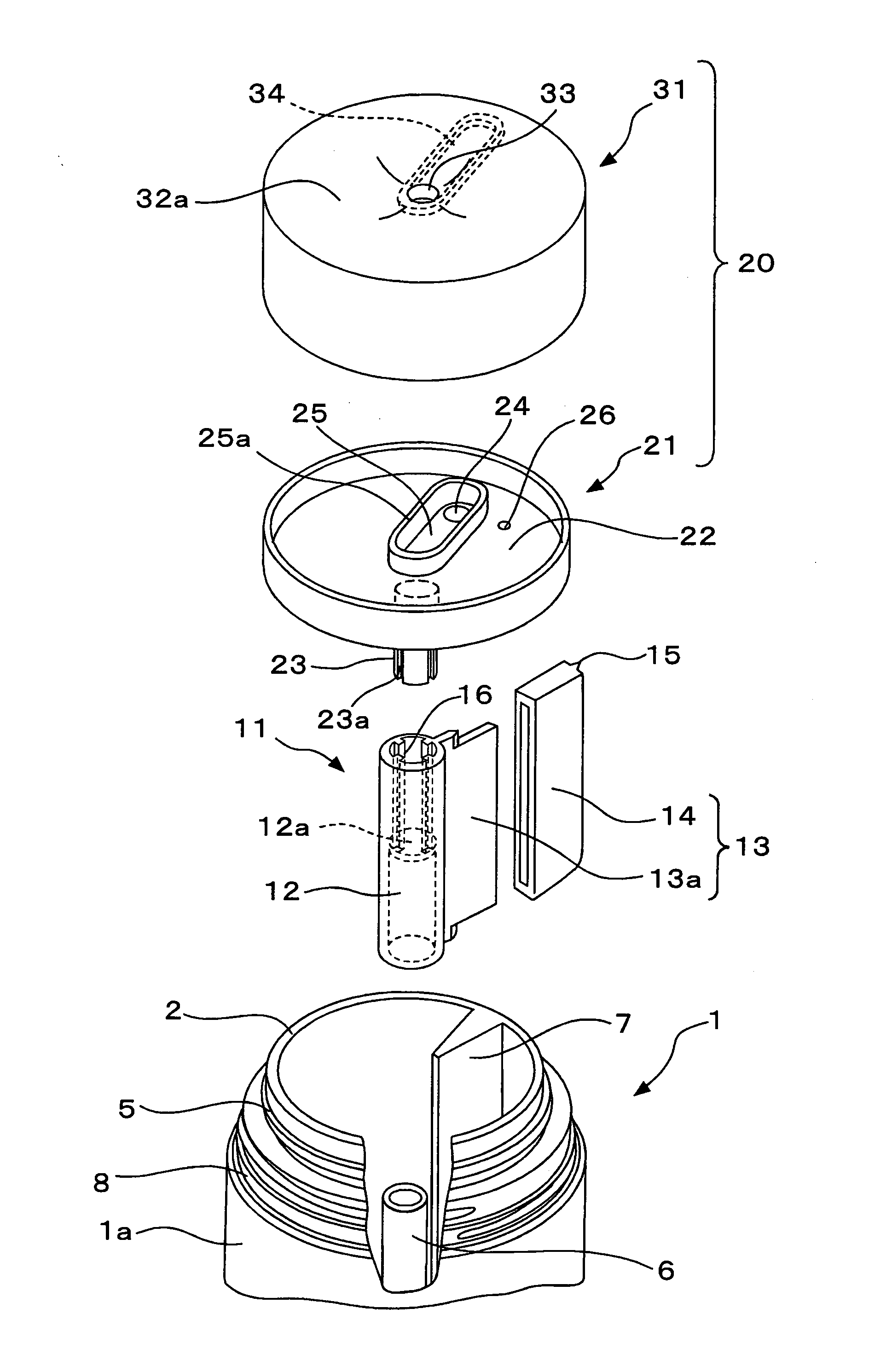
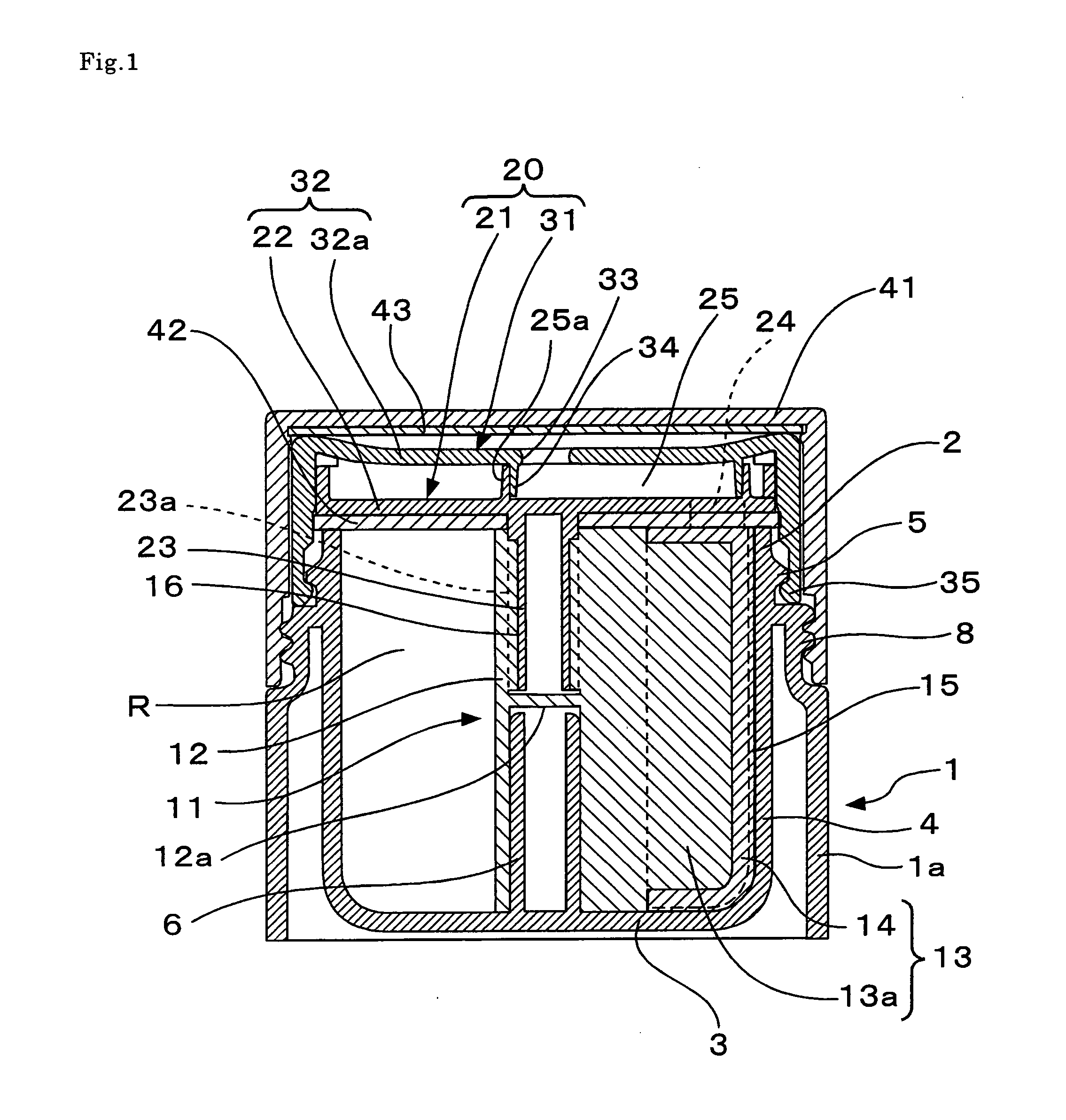
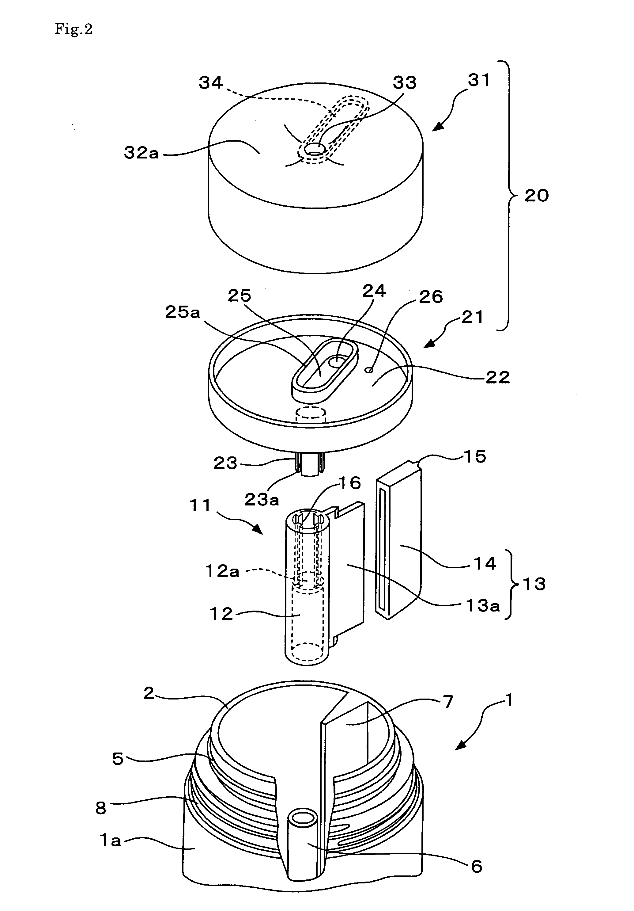
[0085] Embodiments according to the invention are now described with reference to the appended drawings. FIGS. 1 through 4 illustrate a discharge container in a first embodiment according to the invention. FIG. 1 is a vertical cross-sectional view of the container taken along a line A-A in FIG. 3 (a). FIG. 2 is a perspective view illustrating main components disassembled. FIGS. 3(a) and 3(b) are plan views illustrating a container body 1 and a rotor 11 attached thereto, wherein FIG. 3(a) shows a condition prior to use and FIG. 3(b) shows a condition after contents are used up. FIG. 4 is a vertical cross-sectional view of the container taken along a line B-B in FIG. 3(a) (an over cap 41 is removed). The main components included in the container, which are the container body 1, the rotor 11 and a lid 20, are made of synthetic resin. The lid 20 is constituted by two components of a lid part 21 and a cap 31, and the over cap 41 covers the lid 20 from above.

[0086] The container body 1 is...

second embodiment

[0101]FIGS. 5 through 8 illustrate a discharge container in a second embodiment according to the invention. FIG. 5 is a front view illustrating the container 1 and the over cap 41 detached therefrom. FIG. 6 is a vertical cross-sectional view of the container taken along a line C-C in FIG. 8. FIG. 7 is a plan view illustrating a condition where the over cap 41 is removed. FIG. 8 is a plan view illustrating a condition prior to use where the lid 20 is further removed.

[0102] The main components of the container in this embodiment are the container body 1, the rotor 11 and the lid 20, all made of synthetic resin, and the over cap 41 covers the lid 20 from above, as in the first embodiment. Differences between this embodiment and the first embodiment are mainly discussed herein.

[0103] In this embodiment, an outside bottom 1b is used in lieu of the cylindrical skirt 1a of the container body 1 in the first embodiment, such that the container body 1 including the bottom can be a dual-struc...


PUM


Abstract

A discharge container includes a cylindrical container body with a bottom which includes a support extending upward from a bottom wall along a center axis, and a fixed partitioning plate extending from a region from a peripheral wall to a bottom wall as a base end to partition the inside of the container body in a radial direction; a rotor which includes a cylindrical shaft piece rotatably engaging with the outer surface of the support, and a rotatable partitioning plate extending from the cylindrical shaft piece as a base end to be arranged in a radial direction along with the fixed partitioning plate; and a cylindrical lid with a top which has a top wall having a saucer-shaped upper surface, and a downwardly extending shaft extending downwardly from the lower surface of the top wall and engaging with the cylindrical shaft piece from above such that the downwardly extending shaft cannot rotate therein, the lid covering the cylindrical opening as a lid and rotatably engaging with the cylindrical opening, wherein the edge of the fixed partitioning plate is brought into sliding contact with the cylindrical shaft piece; the edge of the rotatable partitioning plate is formed by a spatula-shaped sliding member made of soft material and is brought into sliding and linear contact with an area from the peripheral wall to the bottom wall of the container body; the lower surface of the top wall is brought into sliding contact with the upper end surfaces of the cylindrical opening and the fixed partitioning plate and brought into contact with the upper end surface of the rotatable partitioning plate; and contents are pressed by relative rotation between the container body and the lid and are discharged through a discharge opening provided on the top wall.

Description

TECHNICAL FIELD [0001] The present invention relates to a container capable of discharging an appropriate amount of creamy cosmetics, medical supplies and the like. BACKGROUND ART [0002] Currently, a container in the form of a jar having a wide opening and a lid has been used to store contents such as cream, ointment and gel used as cosmetics and medical supplies. For taking out the contents from the container of this type, a user scoops the contents with a finger. However, it sometimes occurs that too much amount of the contents is taken out and the surplus contents are returned to the container, which is unhygienic. Also, since the area of the contents in direct contact with the air is large, there is a possibility of quality deterioration of the contents due to oxidation or for other reason. [0003] For overcoming the above problems, a discharge container capable of discharging an appropriate amount of contents within a container body by rotation of its lid has been proposed in Pa...

Claims


Application Information

Patent Timeline
IPC IPC(8): G01F11/00
CPCA45D34/04B65D83/0083A45D2200/055A45D40/0075A45D40/26B65D83/00
Inventor HONDA, TAICHIKOBAYASHI, TSUTOMUUEMURA, HIDEO
Owner THE PROCTER & GAMBLE COMPANY
Why Eureka
Try Eureka