
Dynamically controlled power reduction method and circuit for a graphics processor

a graphics processor and dynamic control technology, applied in the direction of digital computer details, liquid/fluent solid measurement, instruments, etc., can solve the problems of reducing the use value of existing power techniques, waste of continuous high speed rendering in the absence of user interaction, and affecting the speed of graphics processor clock speed, etc., to achieve the effect of reducing the time, reducing the clock speed

Active Publication Date: 2007-09-06
ATI TECH INC
View PDF27 Cites 80 Cited by
  • Summary
  • Abstract
  • Description
  • Claims
  • Application Information

AI Technical Summary

Benefits of technology

The present invention relates to a method and apparatus for reducing power consumption of a graphics processor. The invention controls the rate at which frames are rendered by the processor to match the rate at which they are displayed on the screen. This is done by adjusting the clock speed of the processor and the voltage applied to power it. By doing so, the processor is always being used, but not for too long, which helps to maintain image quality. Additionally, the invention includes a method for controlling the idle time between frames, which further reduces power consumption. Overall, the invention helps to improve the efficiency of graphics processing in a way that is visually appealing to users.

Problems solved by technology

These conventional power management techniques, however, are mainly focused on a usage model that requires portions of the computing device to become fully idle for periods of time.
In the presence of continuous rendering, the utility of existing power techniques is reduced drastically.
Specifically, the continuous rendering may prevent the graphics processor from ever being idle, thus inhibiting the majority of the current power management features.
Clearly then, continuous high speed rendering in the absence of user interaction is wasteful.

Method used


Image

  • Dynamically controlled power reduction method and circuit for a graphics processor
  • Dynamically controlled power reduction method and circuit for a graphics processor
  • Dynamically controlled power reduction method and circuit for a graphics processor

Examples


Embodiment Construction

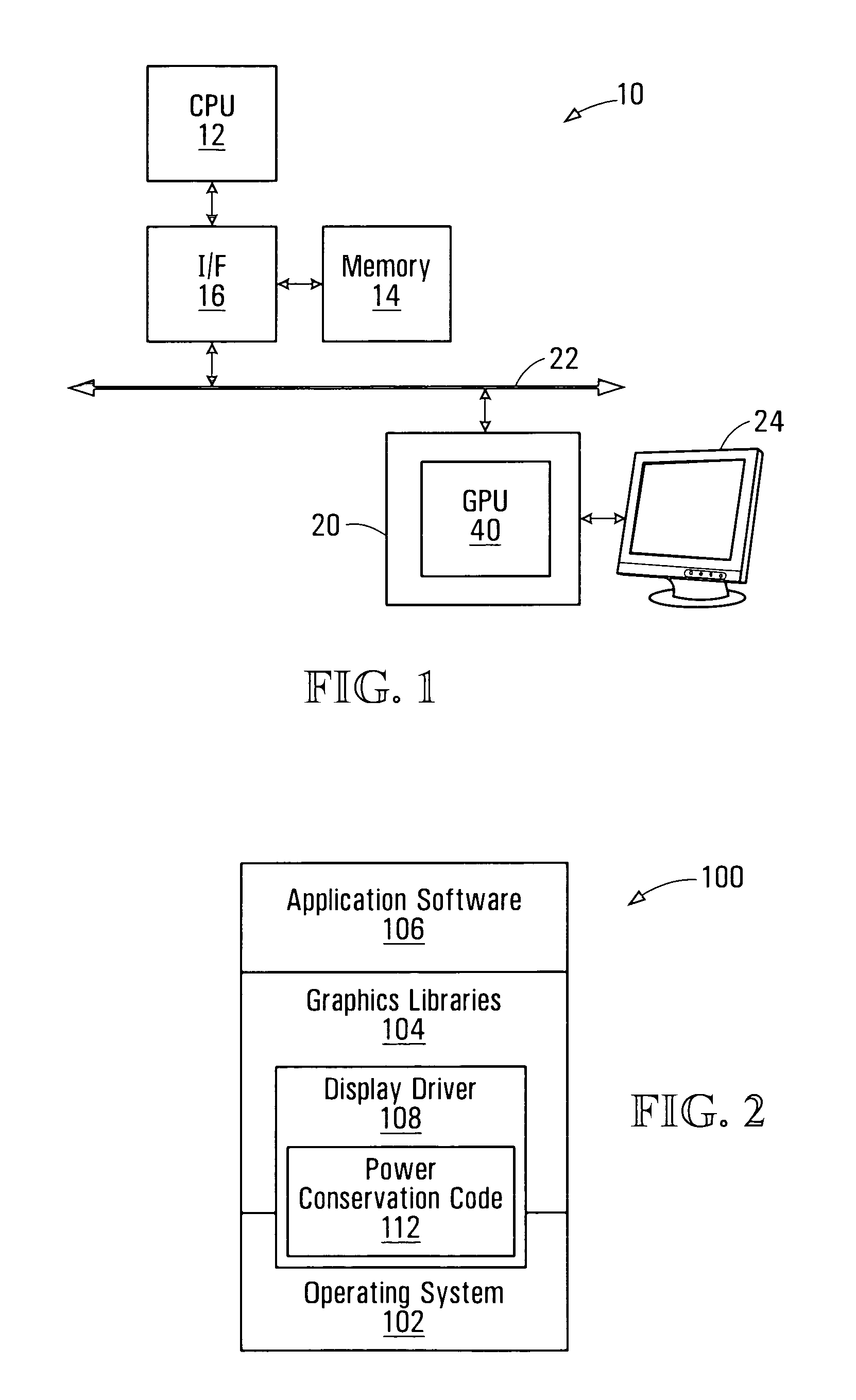
[0022]FIG. 1 is a simplified schematic block diagram of a computing device exemplary of an embodiment of the present invention. Computing device 10 is based on a conventional Intel x86 architecture. However, as will become apparent, the present invention may easily be embodied in computing devices having any suitable architecture. Example computing devices could for example, be based on a PowerPC, RISC or other architecture. Similarly, a computing device embodying the present invention may take the form of a mobile device, such as a laptop, portable telephone, personal digital assistant (PDA), portable video player, or the like.

[0023] Example computing device 10 includes a host processor 12, interconnected to system memory 14 and peripherals through integrated interface circuit 16. In example computing device 10, host processor 12 is a conventional central processing unit and may for example be a microprocessor compatible with the INTEL™x86 family of microprocessors.

[0024] Integra...


PUM


Abstract

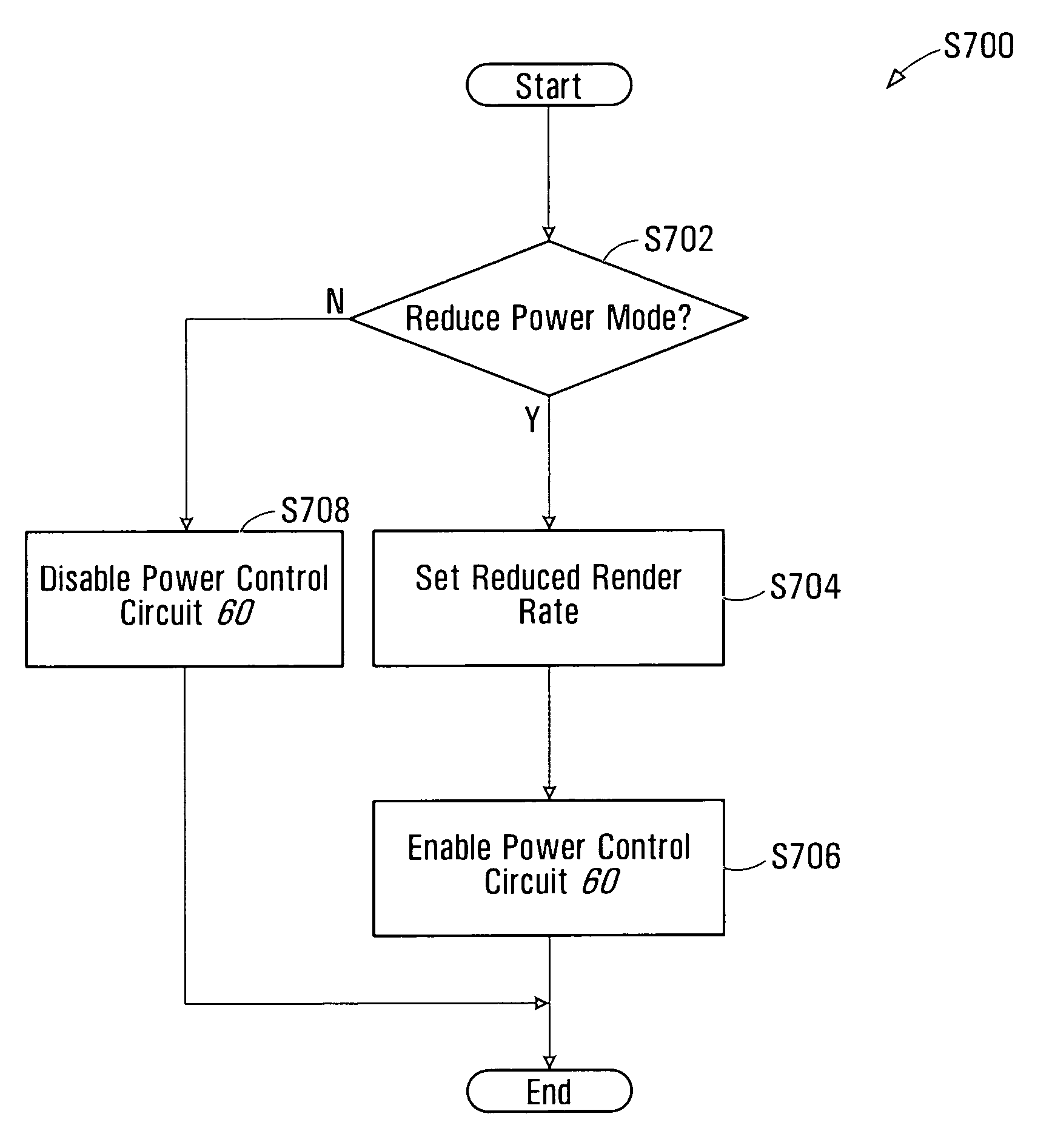
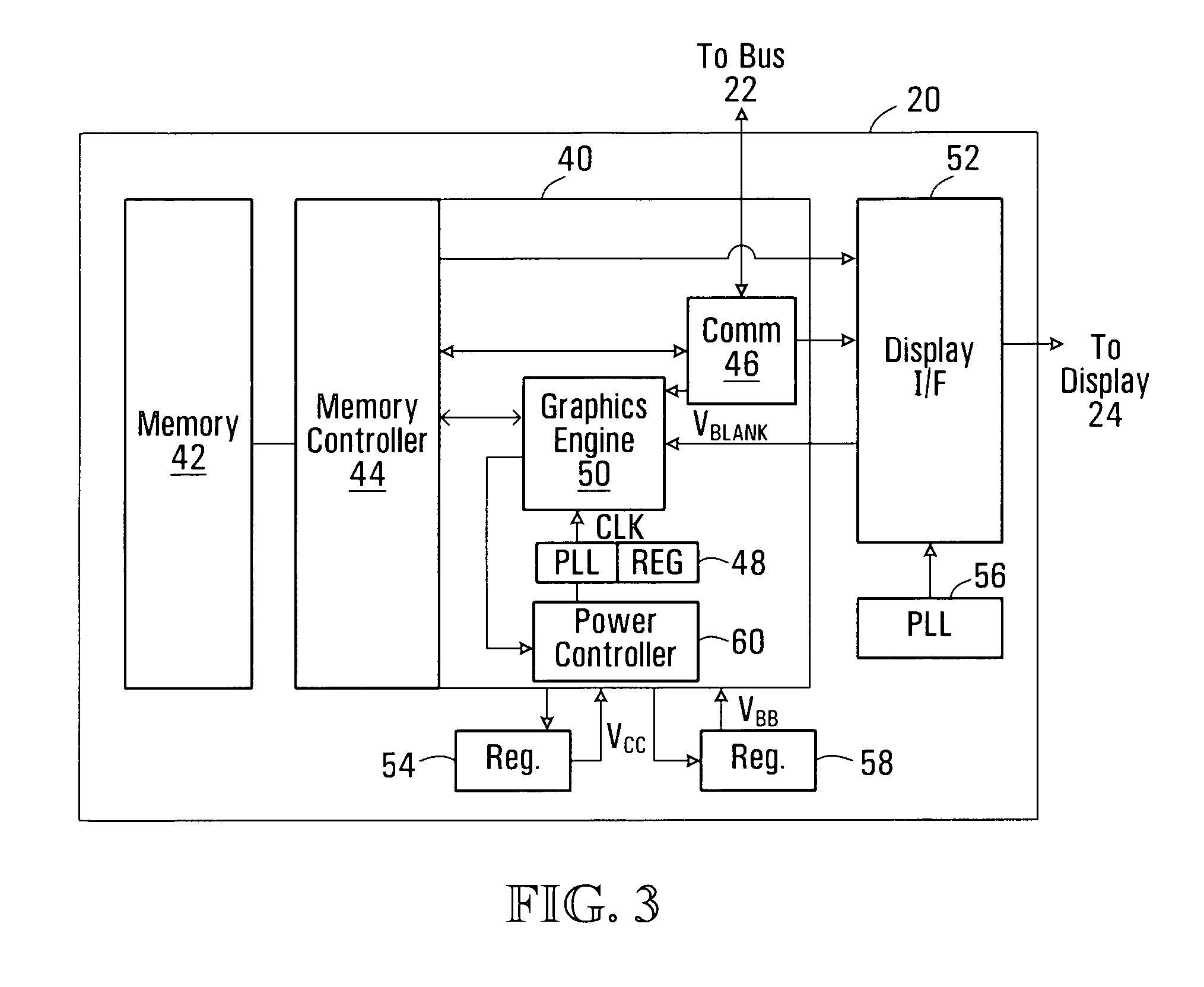
A graphics processor may be operated in a reduced power mode to render frames at rate equal to or less than the rate at which frames are presented on an interconnected display. Graphics processor clock speeds are controlled to reduce the time during which the graphics processor is idle between rendering frames. The graphics processor clock speed may thus be slowed without impacting the quality of rendered images. At the same time the voltage applied to power the graphics processor may be reduced. Optionally, a back bias voltage may further be applied to the processor substrate to reduce power consumption. Clock speed and voltage levels may be adjusted using closed-loop control.

Description

FIELD OF THE INVENTION [0001] The present invention relates generally to power reduction in computing devices, and more particularly to methods and circuits for reducing power consumed by a graphics processor. BACKGROUND OF THE INVENTION [0002] Modern computing device design strives to reduce the electrical power consumed by individual computing components, and subsystems. Reduced power consumption, in turn allows the computing device to operate at reduced temperatures and higher speeds. Moreover, it allows the computing device to operate for longer periods of time using battery or similar energy sources. This in turn, allows the devices to be more portable. [0003] Known power reduction techniques include shutting down components and subsystems, and reducing operating frequencies of clocked circuits during times of no operation. Computer graphics adapters, for example, are shut down or operated at reduced frequency when not in use. [0004] These conventional power management techniqu...

Claims


Application Information

Patent Timeline
Patent Type & Authority Applications(United States)
IPC IPC(8): G06T1/00
CPCG06F1/3225G06F1/3265Y02B60/1242G09G5/363G09G2330/021G06T1/20Y02D10/00
Inventor BAJIC, LJUBISAFRY, JAMES
Owner ATI TECH INC
Learn More