

Printhead with elongate array of nozzles and distributed pulse dampers
a printhead and pulse damper technology, applied in the field of printers, can solve the problems of high print speed, high print speed, and complex distribution of ink along the entire length of the printhead, and achieve the effect of reducing the likelihood of trace cracking and risking localized points of high stress on the traces
- Summary
- Abstract
- Description
- Claims
- Application Information
AI Technical Summary
Benefits of technology
Problems solved by technology
Method used
Image

Examples
Embodiment Construction
Overview
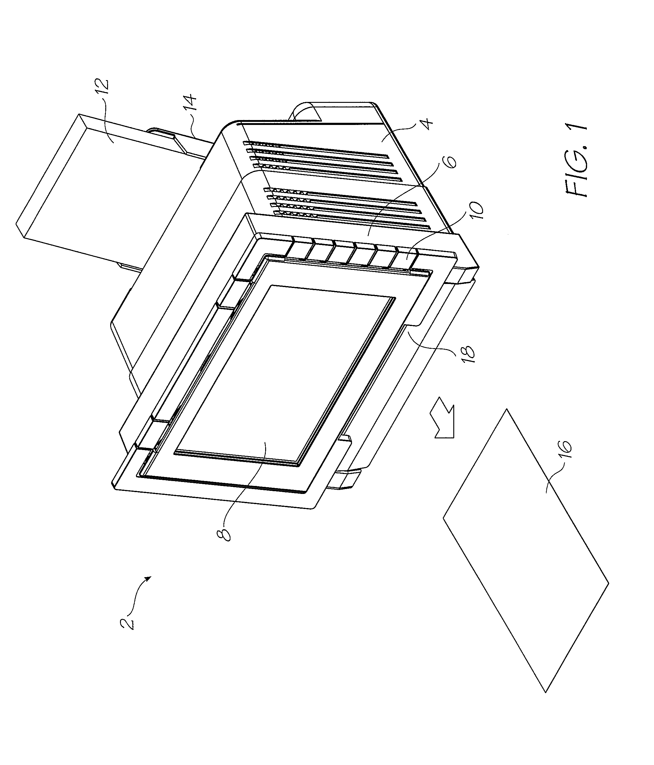
[0139]FIG. 1 shows a printer 2 embodying the present invention. The main body 4 of the printer supports a media feed tray 14 at the back and a pivoting face 6 at the front. FIG. 1 shows the pivoting face 6 closed such that the display screen 8 is its upright viewing position. Control buttons 10 extend from the sides of the screen 8 for convenient operator input while viewing the screen. To print, a single sheet is drawn from the media stack 12 in the feed tray 14 and fed past the printhead (concealed within the printer). The printed sheet 16 is delivered through the printed media outlet slot 18.
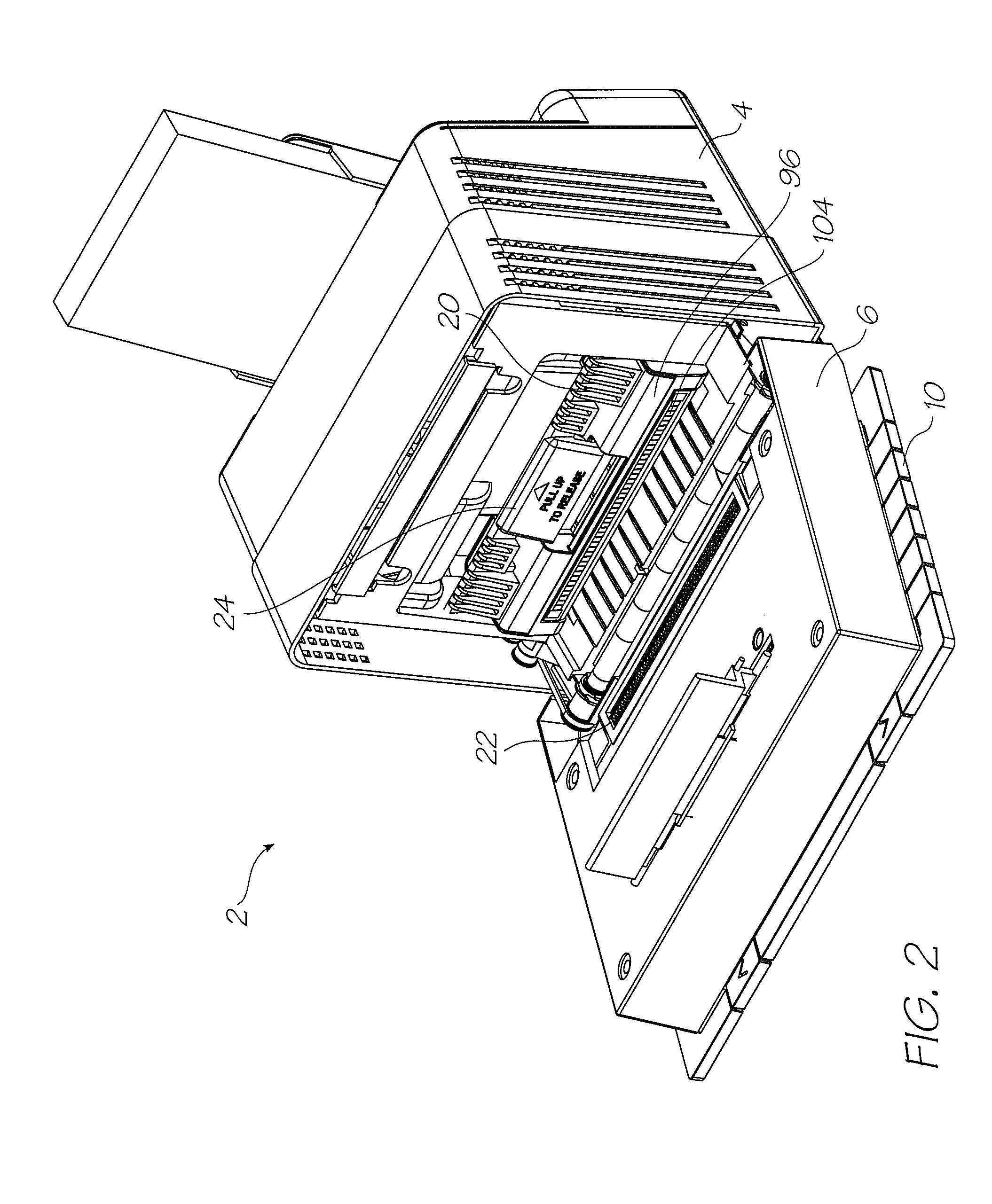
[0140]FIG. 2 shows the pivoting front face 6 open to reveal the interior of the printer 2. Opening the front face of the printer exposes the printhead cartridge 96 installed within. The printhead cartridge 96 is secured in position by the cartridge engagement cams 20 that push it down to ensure that the ink coupling (described later) is fully engaged and the printhead ICs (described l...
PUM
 Abstract
Description
Claims
Application Information