Optical transmitter

a technology of optical transmitter and optical output power, applied in the field of optical transmitter, can solve the problems of limiting optical output power and determining optical output power that is not sufficient for optical communication, and achieve the effect of high optical output power

Inactive Publication Date: 2007-09-06
PANASONIC CORP
View PDF7 Cites 32 Cited by
  • Summary
  • Abstract
  • Description
  • Claims
  • Application Information

AI Technical Summary

Benefits of technology

[0018] Therefore, the present invention is made to solve the conventional problem, and an object thereof is to provide an optical transmitter in which the optical output power is high, the fine adjustment of the optical axes is unnecessary, and further, the propagation area of the emitted light can be adaptively adjusted.

Problems solved by technology

However, in the optical space transmission apparatus, from the viewpoint of user safety, the optical output power is restricted.
The determined optical output power is not sufficient for performing optical communication.

Method used


Image

  • Optical transmitter
  • Optical transmitter
  • Optical transmitter

Examples


first embodiment

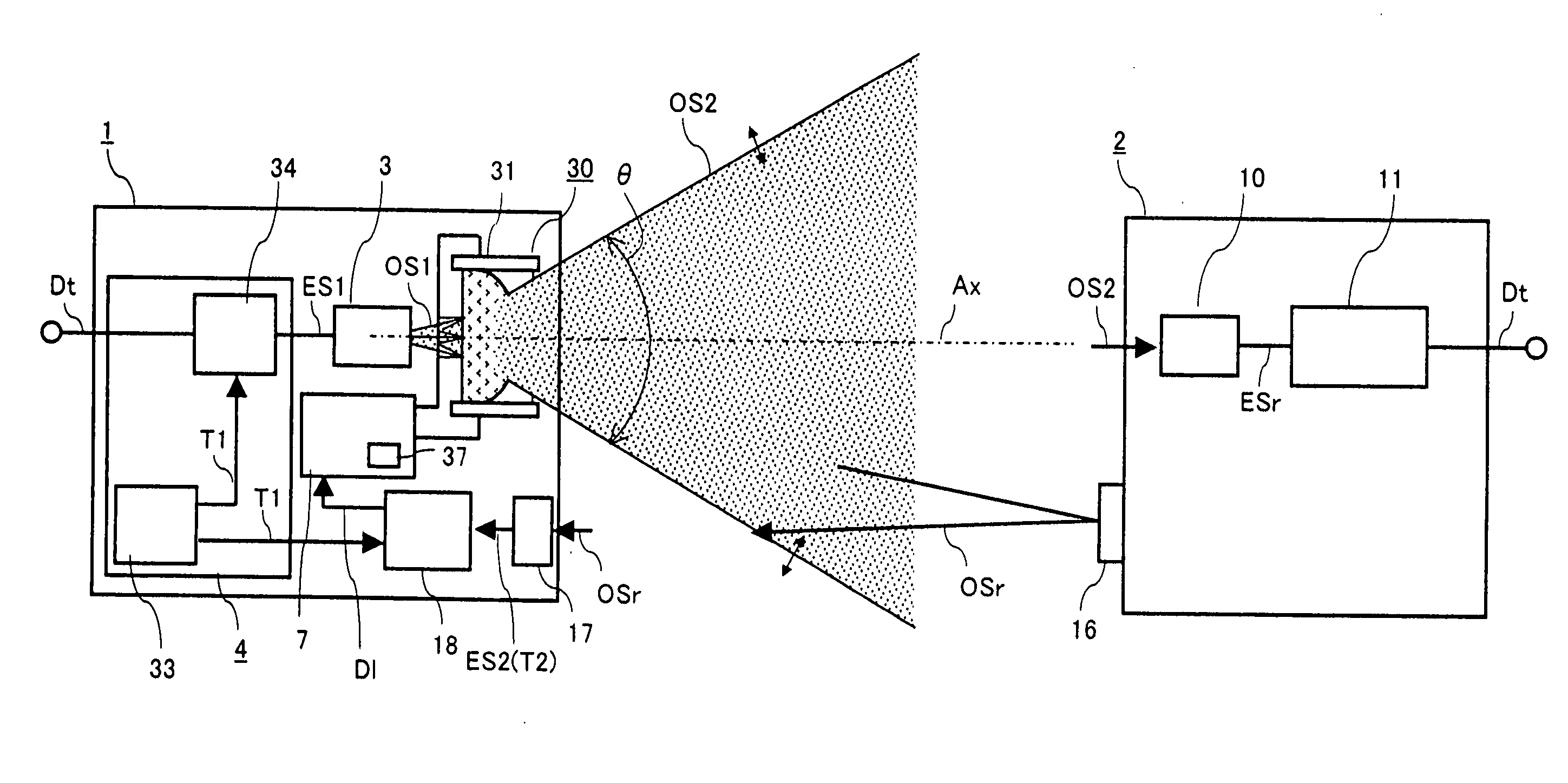
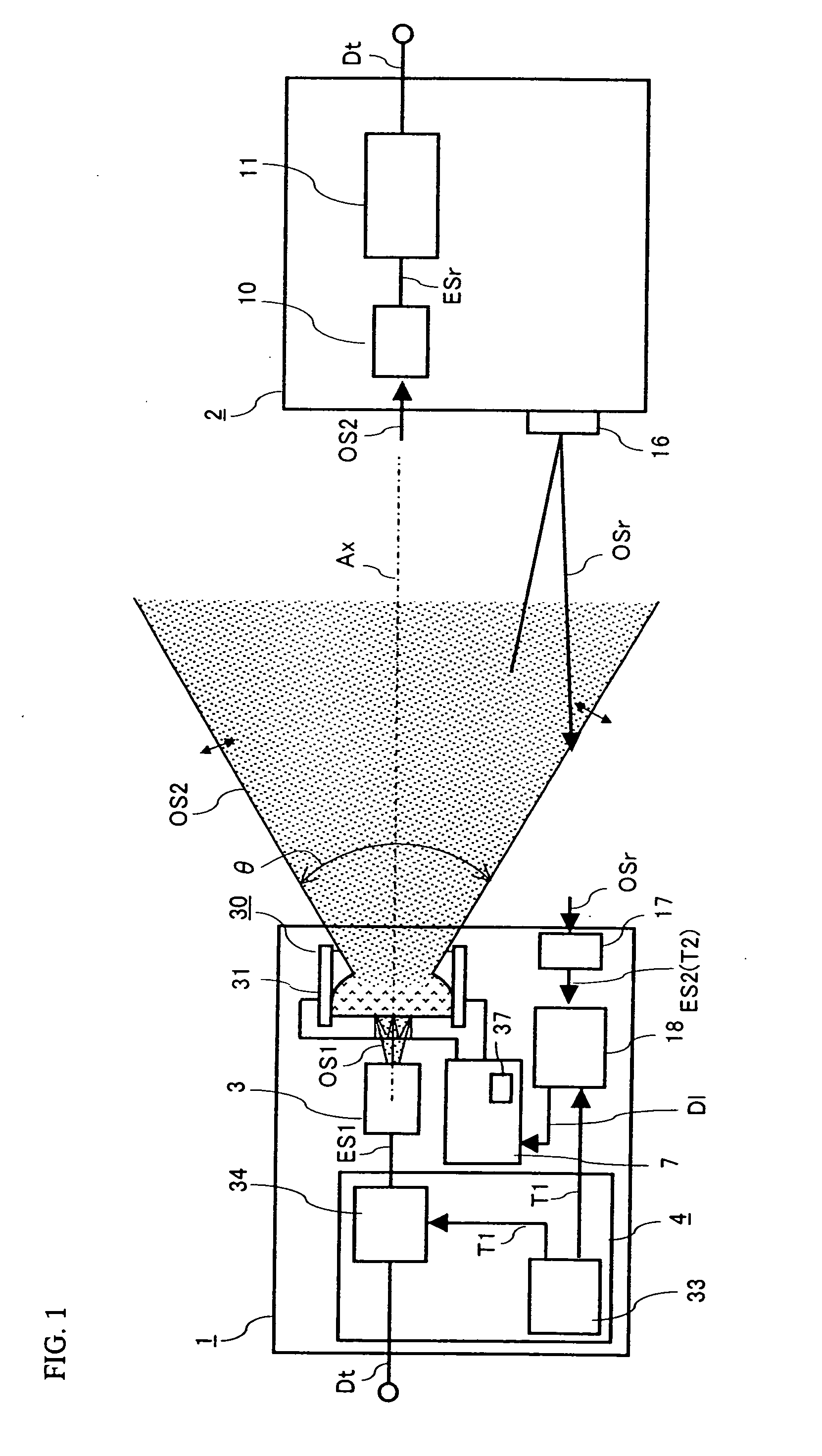
[0058]FIG. 1 is a block diagram of an optical transmission system according to a first embodiment of the present invention.

[0059] Referring to FIG. 1, the optical transmission system includes an optical transmitter 1 and an optical receiver 2 disposed so as to be opposed to each other in free space. The optical transmitter 1 transmits an optical signal through free space, and the optical receiver 2 receives the optical signal transmitted from the optical transmitter 1.

[0060] The optical transmitter 1 has a transmitting circuit 4, a light emitting device 3, a diffusing liquid lens 30, a driving unit 31, a reflected light receiving unit 17, and a delay time calculating unit 18.

[0061] The transmitting circuit 4 receives a data signal Dt, and generates a first electrical signal ES1 for driving the succeeding light emitting device 3 based on the received data signal Dt. More specifically, the transmitting circuit 4 according to the present embodiment includes a timing signal generatin...

second embodiment

[0101]FIG. 7 is a block diagram of the structure of an optical transmitter according to a second embodiment of the present invention.

[0102] The optical transmitter 1 according to the present embodiment has a transmission rate changing unit 28 in addition to the structure of the optical transmitter according to the first embodiment. The transmission rate changing unit 28 receives the data signal Dt to be transmitted, and changes the transmission rate of the data signal Dt. The transmission rate changing unit 28 outputs, to the timing signal generating unit 33, a timing change signal Ct that provides instructions to change the timing signal generation interval in response to a change of the transmission rate of the data signal Dt.

[0103]FIGS. 8A and 8B are timing charts of the data signal and the timing signal supplied to the adding unit shown in FIG. 7.

[0104] Referring to FIG. 8A, when the transmission rate changing unit 28 outputs the data signal Dt at a transmission rate R1, the ...

third embodiment

[0107]FIG. 9 is a block diagram of the structure of an optical transmission system according to a third embodiment of the present invention. Since the basic structure of the optical transmission system according to the present embodiment is similar to that according to the first embodiment, hereinafter, the difference between the present embodiment and the first embodiment will be mainly described.

[0108] The optical transmitter 1 according to the present embodiment has a light receiving device 39 instead of the reflected light receiving unit 17 and the delay time calculating unit 18 shown in the first embodiment (FIG. 1). The optical receiver 2 has a light emitting unit 12 instead of the reflecting unit 16 shown in the first embodiment (FIG. 1). The wavelength of the light outputted by the light emitting unit 12 is different from that of the light outputted by the light emitting device 3 of the optical transmitter 1.

[0109] When the optical transmitter 1 and the optical receiver 2 ...


PUM


Abstract

An optical transmission apparatus is provided in which high optical output power is secured in an optical transmitter, the fine adjustment of the optical axis is unnecessary, and the propagation range of the optical output signal can be adaptively changed. A diffusing liquid lens includes a first liquid and a second liquid containing a scattering material that scatters light, and the curvature of the boundary surface between the first and the second liquids is changed according to the control voltage applied from a controlling unit. A first optical signal outputted from a light emitting device is diffused in the first liquid, and emitted as a second optical signal having a spread angle corresponding to the curvature of the boundary surface and a substantially uniform radiant intensity distribution.

Description

BACKGROUND OF THE INVENTION [0001] 1. Field of the Invention [0002] The present invention relates to an optical transmitter, and more particularly, to an optical transmitter that transmits an optical signal to an optical receiver through free space. [0003] 2. Description of the Background Art [0004] Conventionally, an optical space communication that transmits an optical signal through free space has been known. Since light which serves as the transmission medium in the optical space communication has directivity, it is necessary to adjust the optical axis between the optical transmitter and the optical receiver. [0005]FIG. 21 is a view of an example of an optical space transmission apparatus having an optical axis adjusting function. [0006] An optical transmitter 101 and an optical receiver 102 respectively have optical axis adjusting mechanisms 103a and 103b that are rotatable about a horizontal axis and a vertical axis. To enable the optical communication between the optical tran...

Claims


Application Information

Patent Timeline
Patent Type & Authority Applications(United States)
IPC IPC(8): H04B10/00
CPCG02B3/14G02B5/0242G02B5/0278H04B10/1121G02B7/006G02B26/0875G02B5/0294
Inventor HASE, KAZUTOSHIYASUMOTO, HIDEOKINOSHITA, KEISUKEIEDA, TOMOAKISASAI, HIROYUKI
Owner PANASONIC CORP
Why Eureka
Try Eureka