
Electrostatic image developing toner

a technology of developing toner and electrostatic image, which is applied in the direction of developers, instruments, optics, etc., can solve the problems of low transparency, degradation of image color reproduction, and limited range and chroma of reproducible color, and achieve high offset resistance, excellent color reproduction, and heat resistance high

Inactive Publication Date: 2007-09-06
KONICA MINOLTA BUSINESS TECH INC
View PDF3 Cites 11 Cited by
  • Summary
  • Abstract
  • Description
  • Claims
  • Application Information

AI Technical Summary

Benefits of technology

[0017]In view of the foregoing, the present invention was achieved. An object of the present invention is to provide an electrostatic image developing toner which exhibits sufficient transparency and chroma, excellent color reproduction as well as excellent electrification characteristics, and forms an image exhibiting excellent heat resistance and sufficient retention qualities, and consequently is capable of maintaining image characteristics for an extended period of time, and an image forming method using the same.
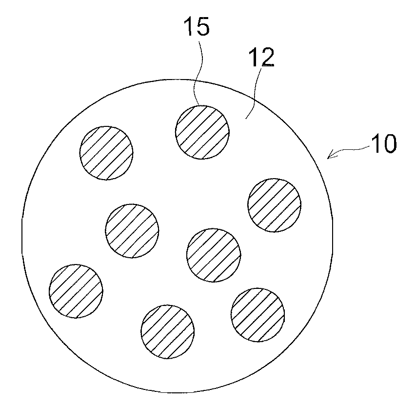
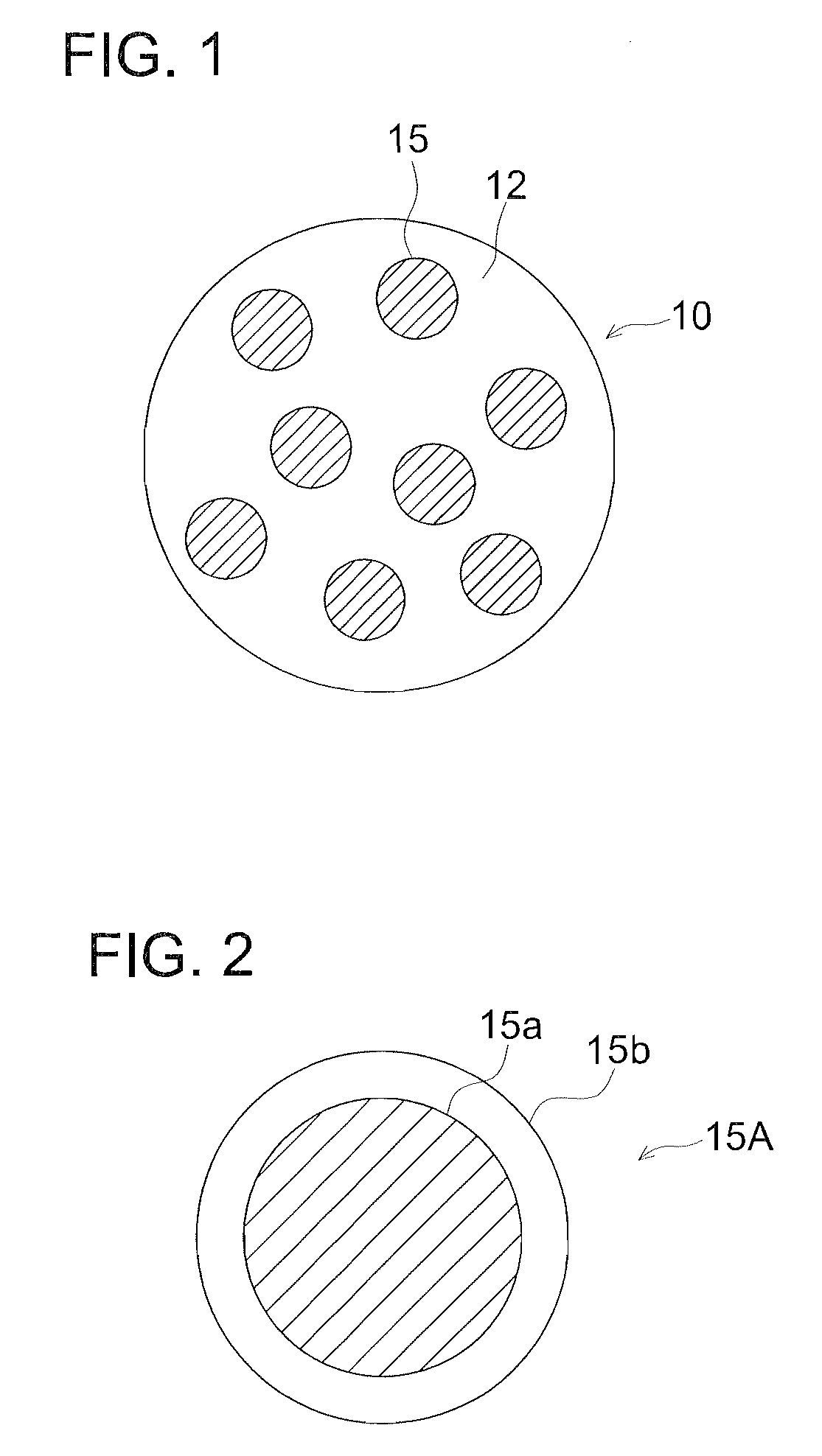
[0023]By employing the electrostatic image developing toner of the present invention, dyes as a colorant are dispersed into toner particles in the form of minute colored particles, and further, volume average particle diameter D1 and an average diameter D2 of the dye cloud formed via the above dyes are regulated to satisfy the specified relational formula, whereby sufficient heat resistance and high offset resistance are realized, and further, excellent color reproduction based on sufficient transparency and chroma and desired electrification characteristics are also realized. As a result, the quality of images formed employing the above electrostatic image developing toner can be maintained for a relatively long time.

Problems solved by technology

However, organic pigments are present in such a state that they are dispersed into binder resins in the form of aggregated particles and exhibit low dispersibility, whereby the resulting toner exhibits high covering power resulting in low transparency.
Consequently, of the color toners of each color which are superimposed to form images, the toner in the lowermost layer is hidden by the layers above it, whereby problems occur in which colorfulness is lowered due to difficulty of viewing the color of the toner in the lowermost layer, resulting in degradation of the color reproduction of images.
When color images are formed employing color toners incorporating pigments, in practice, the range and chroma of reproducible color are occasionally limited due to spectral characteristics of the pigments dispersed into binder resins and color mixing properties during superimposition of toners of different colors, whereby it is a concern that the colors of documents may not be faithfully reproduced.
However, even by employing these methods, it has been difficult to improve toners incorporating pigments as a colorant to exhibit the targeted transparency and chroma.
However, due to these characteristics, they exhibit drawbacks in which their light fastness and heat resistance are significantly inferior to pigments.
When dyes are insufficient in heat resistance, they are decomposed due to heat to result in a decrease in image density.
Further, when toner images are fixed based on a contact heating system, dyes may be sublimed to stain the interior of production devices.
Still further, problems occur in which dyes are dissolved in silicone oil employed during fixing and are finally transferred to and fused onto the heating roller to result in offset phenomena.
Subsequently, for example, upon considering the color reproduction in the blue region, pigments should be use the cyan and yellow colorants, whereby it is not possible to obtain sufficient overall transparency.

Method used


Image

  • Electrostatic image developing toner
  • Electrostatic image developing toner
  • Electrostatic image developing toner

Examples


example

[0138]The embodiment of the present invention is described in terms of examples.

Preparation of Minute Colored Particle Dispersion 1

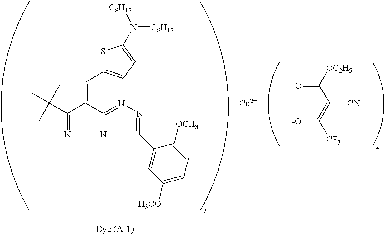
[0139]To a separable flask were added 13.5 g of polymer (P-1), a 50 / 30 / 20 mixture of methylmethacrylate (MMA) / acetoxyethylmethacrylate (AAEM) / stearylmethacrylate (SMA), 16.0 g of dye (A-1) shown below and 123.5 of acetic acetate and after the atmosphere in interior was replaced with nitrogen gas, the dye was completely dissolved with stirring. Further thereto, 230 g of an aqueous solution 8.0 g of AnrAiON hH-50 (a surfactant, produced by DAI-ICHI hOdvO SEIvAhr CO., iTD.) was dropwise added with stirring and then emulsified for 300 sec. using CiEAR-MIu W-MOTION CiM-0.8W (produced by M-TECHNInrE Co.). Thereafter, acetic acetate was removed under reduced pressure to obtain the minute colored particle dispersion 1 containing a dye. In the thus obtained dispersion, the volume-average particle size of colored particles was 30 nm. Hereinafter, the volume-averag...

preparation example

of Comparative Toner 3

[0159]Toner particles were prepared similarly to the foregoing toner particle 1, except that the minute colored particle dispersion 1 was replaced by the minute colored particle dispersion 8. The thus obtained toner particles wHrH dHsiJnDWHd “CRPSDrDWivH 7RnHr 3”.

[0160]The Comparative Toner 3 contains a dye and an anti-oxidant in the colored particle in a dissolved state.

Measurement of Diameter of Dye Cloud D2

[0161]The average diameter of D2 of the dye cloud of the colored particles was measured for each of the toner samples 1-5 and comparative toner samples 1-5 in such a manner that a toner particle was cut to a thickness of 0.2 μm, employing a microtome. The resulting sample was employed to form a transmission electron microscope image (being a TEM image) at a magnification factor of 100,000, then the arithmetical average value in the Fere direction of 100 dye clouds was designated as the average diameter D2 of the dye cloud.

TABLE 1Minute colored particlesolu...


PUM


Abstract

An electrophotographic toner is disclosed. The toner is composed of toner particles comprising colored particles containing a dye which is dispersed in a binder resin, wherein the toner particles satisfies formula of 3≧D2 / D1>1, D1 being a volume average particle diameter of the colored particles, and D2 being an average diameter of dye cloud formed by the colored particles in the toner particle.

Description

[0001]This application claims priority from Japanese Patent Application No. JP2006-057382, filed on Mar. 3, 2006, which is incorporated hereinto by reference.FIELD OF THE INVENTION[0002]The present invention relates to an electrostatic image developing toner employed for electrophotographic methods, and an image forming method.BACKGROUND OF THE INVENTION[0003]In image formation employing electrophotographic methods, generally, by exposing light information in response to image information onto a photoreceptor incorporating photoconductive materials, an electrostatic image is formed on the above photoreceptor, and the above electrostatic image is developed employing a charged toner to result in a toner image. The resulting toner image is transferred onto an image recording medium such as paper, followed by fixing the image by application of heat, pressure, or solvent vapor, whereby a visible image is produced.[0004]In formation of such as full-color images employing the above electro...

Claims


Application Information

Patent Timeline
IPC IPC(8): G03G9/09
CPCG03G9/0819G03G9/09321G03G9/09392G03G9/09385G03G9/09378
Inventor ONO, KAORIYAMAZAKI, HIROSHICHIBA, TAKATO
Owner KONICA MINOLTA BUSINESS TECH INC
Learn More