Method and apparatus for increasing blood flow through an obstructed blood vessel

a technology applied in the field of obstruction and blood flow through an obstruction, can solve the problems of affecting the affected region permanently, affecting the blood flow of many other vessels in the body, and similar damage to many other vessels, so as to improve the blood flow through the blood vessel

Active Publication Date: 2007-09-06
THE CLEVELAND CLINIC FOUND
View PDF16 Cites 245 Cited by
  • Summary
  • Abstract
  • Description
  • Claims
  • Application Information

AI Technical Summary

Benefits of technology

[0008] In an embodiment of the present invention, an expandable member is described. The expandable member includes a proximal member end and a distal member end, longitudinally spaced from the proximal member end. A tubular member body extends between the proximal and distal member ends and is adapted to selectively contact at least a portion of an obstruction within a blood vessel in a radial direction, to dislodge at least one fragment from the obstruction, and to enhance blood flow through the blood vessel past the obstruct

Problems solved by technology

Ischemia refers to a substantial reduction or loss of blood flow to the brain or any other tissue that is being supplied by the blood vessel and can lead to permanent damage of the affected region.
While vascular disease is most commonly associated with the formation of hard plaque and coronary artery disease in the heart, similar damage can happen to many other vessels in the body, such as the peripheral vessels and cerebral vessels, due to the buildup of obstructions, including hard plaque or softer thrombus/grumous material, within the lumen of an artery or vein.
Although interventional vascular procedures avoid many of the complications involved in surge

Method used


Image

  • Method and apparatus for increasing blood flow through an obstructed blood vessel
  • Method and apparatus for increasing blood flow through an obstructed blood vessel
  • Method and apparatus for increasing blood flow through an obstructed blood vessel

Examples


Embodiment Construction

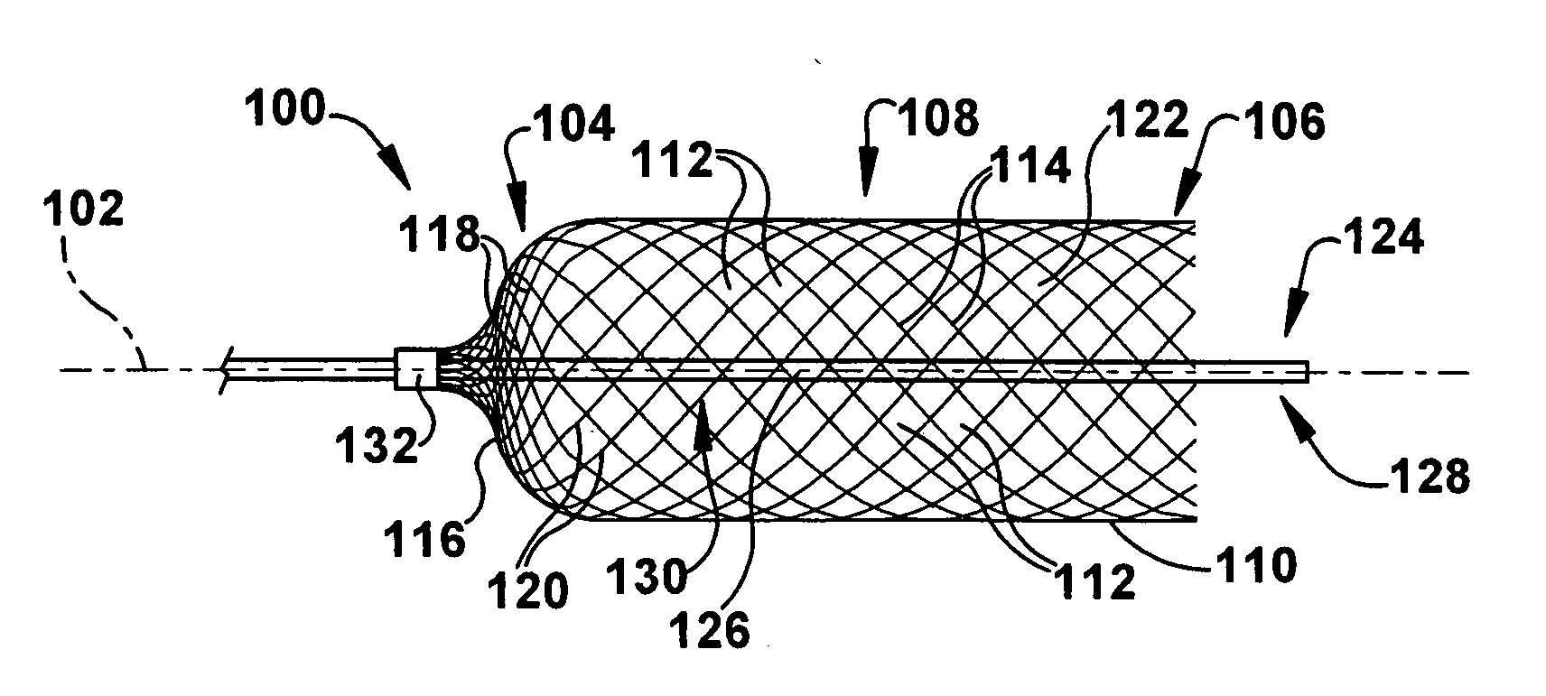
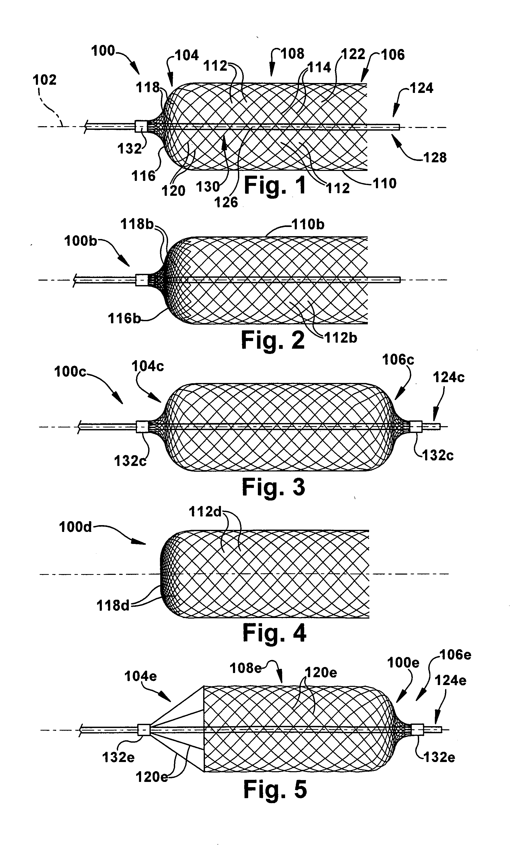
[0019] In accordance with the present invention, FIG. 1 depicts a first arrangement of an expandable member 100 for increasing blood flow through an obstructed blood vessel. The expandable member 100 defines a longitudinal axis 102, which may be rectilinear or curvilinear. The expandable member 100 has a proximal member end 104 longitudinally spaced from a distal member end 106. The terms “proximal” and “distal” refer to orientations inside a patient's body with respect to a user, with a proximal location being nearer to an insertion point into the body than a distal location. It should be realized, however, that structures and deployment may be oriented differently for a particular application and that the terms “proximal” and “distal” are used herein for ease of description without limiting the present invention. At least one of the proximal and distal member ends 104 and 106 is closed, with a closed end, depicted as the proximal member end in FIG. 1, being positioned further down...


PUM


Abstract

A method of increasing blood flow through an obstructed blood vessel includes providing an expandable member substantially made of a mesh having a plurality of interstices. The expandable member has a proximal member end and a distal member end spaced longitudinally apart by a tubular member body. The expandable member is substantially closed at the distal member end. The expandable member is inserted into the blood vessel. The expandable member is positioned within the blood vessel with the proximal member end upstream of the distal member end and the member body located radially adjacent at least a portion of an obstruction. The expandable member is expanded to bring at least a portion of the member body into contact with the obstruction. An outward radial force is exerted on the obstruction to dislodge at least one fragment from the obstruction and to enhance blood flow through the blood vessel past the obstruction. The at least one fragment is passed through at least one interstice of the member body in the radial direction. The at least one fragment is selectively retained within the expandable member. An apparatus for increasing blood flow through an obstructed blood vessel is also provided.

Description

RELATED APPLICATIONS [0001] This application claims priority from U.S. Provisional Application No. 60 / 764,206, filed Feb. 1, 2006 and U.S. Provisional Application No. 60 / 793,588, filed Apr. 20, 2006, the subject matter of both of which is incorporated herein by reference.TECHNICAL FIELD [0002] The present invention relates to an apparatus and method for increasing blood flow through an obstructed blood vessel and, more particularly, to a method and apparatus for using an expandable member to increase blood flow through an obstructed blood vessel. BACKGROUND OF THE INVENTION [0003] Vascular disease involves damage that happens to the blood vessels in the body. Diseased blood vessels can become plugged with thrombus, plaque, clots, grumous material, and / or other unwanted matter (hereafter “obstructions”) that may ultimately lead to a condition known as ischemia. Ischemia refers to a substantial reduction or loss of blood flow to the brain or any other tissue that is being supplied by ...

Claims


Application Information

Patent Timeline
IPC IPC(8): A61M29/00A61F2/86A61F2/966
CPCA61B17/221A61B17/320725A61B2017/00867A61B2017/00893A61B2017/22034A61B2017/22038A61B2017/22061A61B2017/22084A61B2017/2212A61B2017/320004A61B2017/320008A61B2017/320733A61B2017/320741A61M25/10A61M25/1027A61M29/02A61M2025/1088A61M2025/1095A61B17/22
Inventor FIORELLA, DAVIDWOO, HENRY
Owner THE CLEVELAND CLINIC FOUND
Why Eureka
Try Eureka