
Box cutter with grip-actuated blade extension

a box cutter and extension technology, applied in the field of hand-held box cutters, can solve the problems of operator flesh wounds, hand and wrist muscle fatigue becoming a serious concern, and many on-the-job personal injuries, and achieve the effect of improving operator safety

Inactive Publication Date: 2007-09-13
DALLCO MARKETING SERVICES +1
View PDF52 Cites 38 Cited by
  • Summary
  • Abstract
  • Description
  • Claims
  • Application Information

AI Technical Summary

Benefits of technology

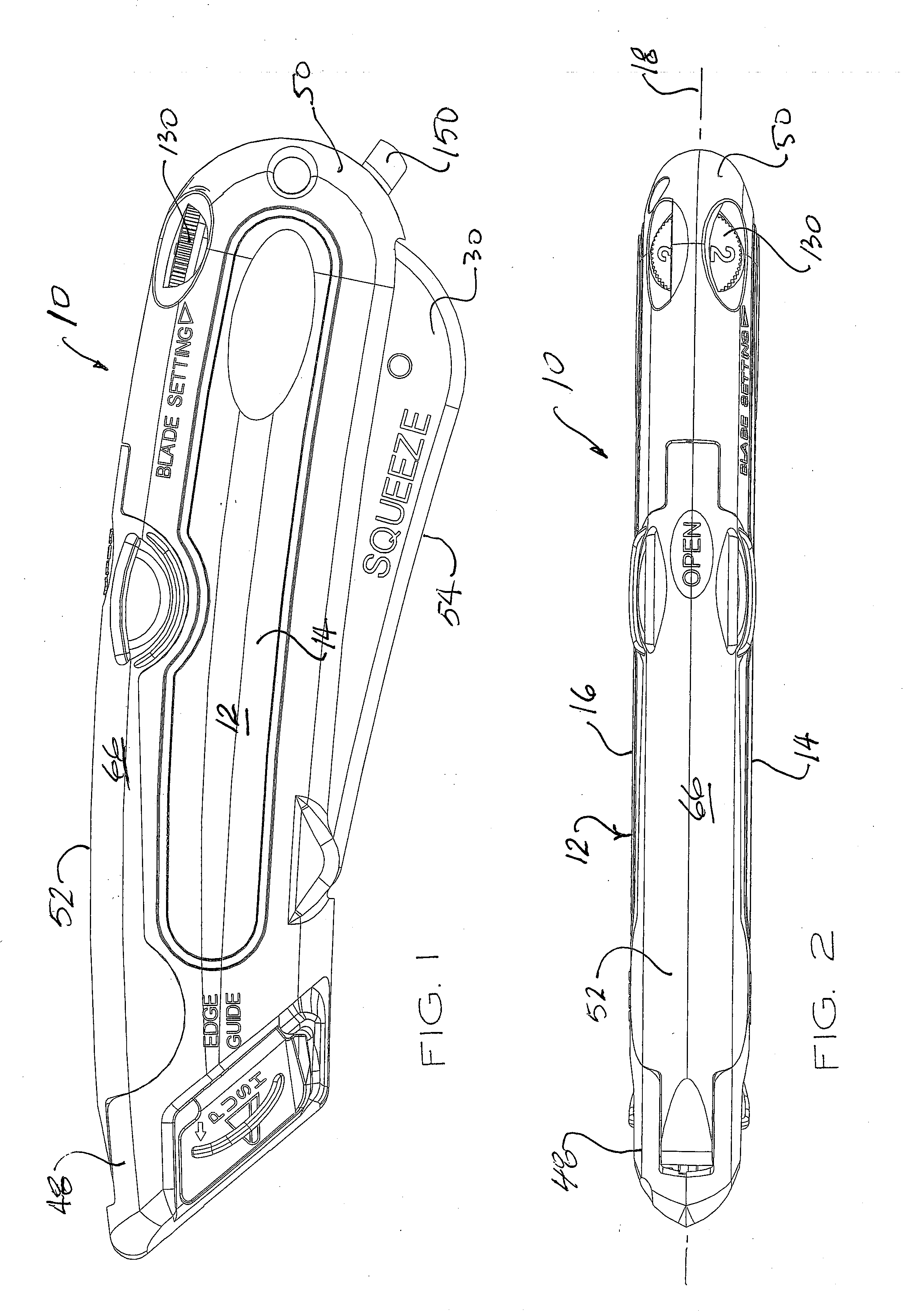
[0013] An automatic blade-retracting box cutter utility knife of the present invention has a handle with ergonomic hand grip proportions for comfortable gripping and handling during repetitive cutting operations. The principal components of the knife that require operator access are mounted on the handle at locations that are symmetrically disposed relative to the cutting plane of the working blade.
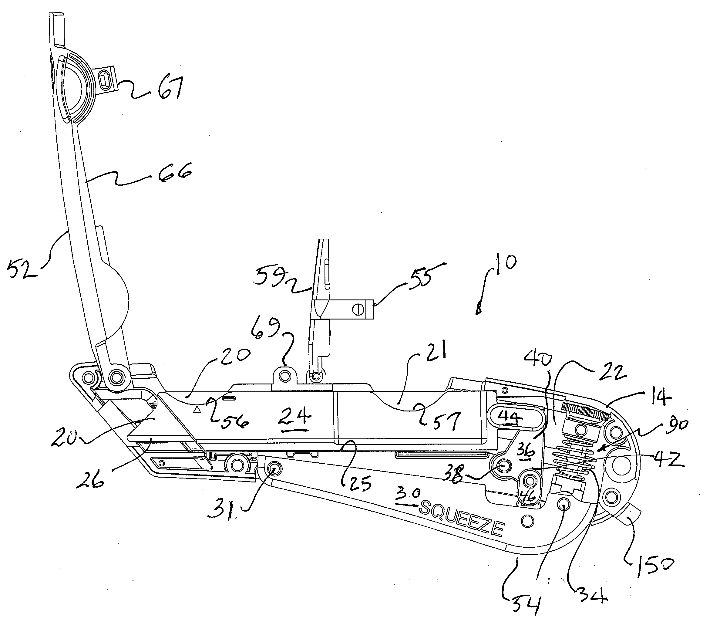
[0017] Top access to a working blade and a replacement blade stored on the shuttle is provided on top of the handle for blade loading and security. The working blade and one or more replacement blades are securely retained in top loading compartments formed between the sidewalls of the blade shuttle. A window formed in the top of the handle provides operator access for loading and replacing blades. The window is closed by a blade cover that is pivotally attached to the handle, thereby providing a protective covering over the blade receiving compartment in a closed position, and providing operator access to the blade receiving compartment in an open position.
[0018] The handle has a blade extension port that is wedge-shaped in profile, being narrow at the top and relatively wide at the bottom. During a cutting operation, the working blade is locked against deflection on both sides and along the top and bottom of the blade. This prevents buckling of the blade as the cutter blade is undergoing heavy cutting action.
[0020] A fixed blade stub projects from the rear of the housing for quick tape cutting jobs. The exposed cutting edges and corners are relatively blunt for personal safety and product protection. The fixed blade stub is mounted on the butt end of the handle and can be used while the cutting blade is locked in the fully retracted position, thus improving operator safety when using the knife to perform tape cutting operations that do not require a sharp cutting edge.

Problems solved by technology

This simple task has resulted in many on-the-job personal injuries.
Because such use frequently involves quick hand movements, and the cardboard presents considerable resistance to cutting, hand and wrist muscle fatigue become a serious concern.
Moreover, operator flesh wounds are likely when the knife blade travels free at the end of a cut and catches the operator's hand, fingers, arm, waist or leg.
It may be difficult, undesirable, and impermissible to sell merchandise that has been cut while opening the shipping box.
On the other hand, persons opening boxes and stocking shelves are often under time constraints and economic constraints regarding the time and cost consumed in stocking the shelves.
In some cases, especially when the keeper plate is extended completely forward with some force, the blade will simply fall from the handle by its own weight, resulting in a dropped blade.
However, box cutters are not only used to make edge cuts, but are also often used for other types of cuts, such as cutting a taped edge, where the fixed guard may interfere with or preclude other types of cuts.
Also, some edge guards do not provide safety features that will adequately protect a user during repeated rapid cuts.
However, this arrangement is inconvenient as the operator must maintain pressure on the thumb button to use the knife, which causes muscle fatigue after repetitive use, and prevents the thumb from being used to maneuver the knife and establish a firm grip, resulting in a reduction of stability and control during heavy cutting jobs.

Method used


Image

  • Box cutter with grip-actuated blade extension
  • Box cutter with grip-actuated blade extension
  • Box cutter with grip-actuated blade extension

Examples


Embodiment Construction

[0044] Preferred embodiments of the invention will now be described with reference to various examples of how the invention can best be made and used. Like reference numerals are used throughout the description and several views of the drawing to indicate like or corresponding parts. As used herein, “utility knife” and “box cutter” are used interchangeably to refer a hand-held knife of the type used to open cardboard cartons.

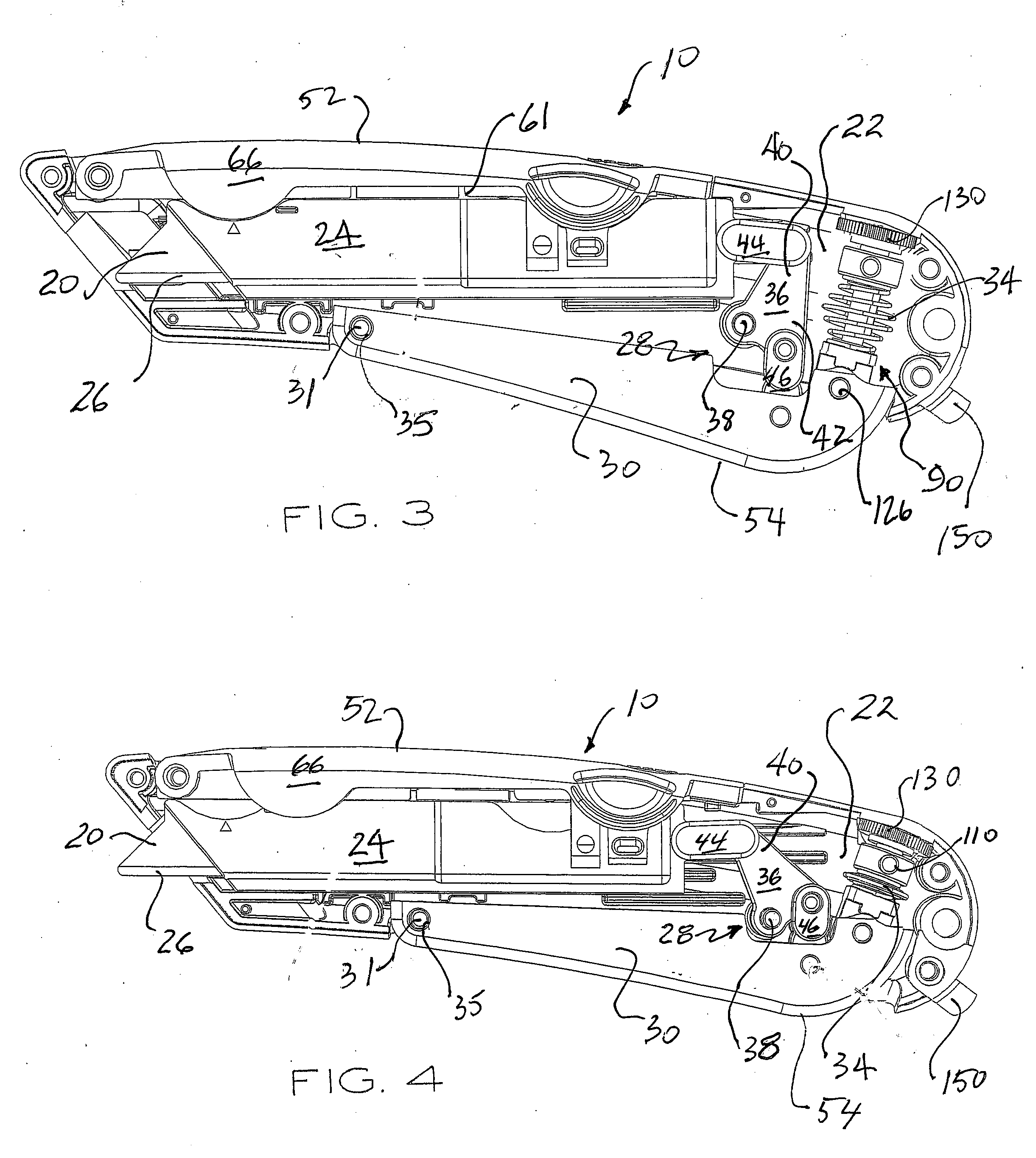
[0045] Referring now to FIG. 1 and FIG. 2, a box cutter utility knife 10 of the present invention includes a handle 12 formed by a pair of molded plastic handle sections 14 and 16. The handle sections 14, 16 have bilateral symmetry along the cutting plane 18 of the working blade 20 and are connected together to enclose a cavity 22. The working blade 20 is held in a molded plastic blade shuttle 24 that is movable through a guide channel 25 formed along the handle sidewalls in an outward or forward direction to a fully extended position (FIG. 4) and in an opposit...


PUM


Abstract

An automatic blade-retracting box cutter utility knife has a handle with ergonomic hand grip proportions for comfortable gripping and handling during repetitive cutting operations. A blade-actuating hand-grip lever is mounted on the housing for movement about a pivotal axis. A blade shuffle is mounted for longitudinal sliding reciprocal movement in the housing from a rear retracted end position in which the blade is wholly received in the housing, to a front extended end position in which the blade is extended forward from the housing. The blade shuttle is extended in response to gripping actuation of the hand-grip lever. Extension and retraction forces are transferred from the hand-grip lever to a compression spring and to the blade shuttle via a power transmission assembly that includes a torque plate that is mounted for clockwise and counterclockwise rotation on the housing. Top access to a working blade and a replacement blade stored on the shuttle is provided for blade loading and security. Dual edge guide members are mounted for independent extension and retraction movement. A depth of cut adjustment dial is integrated with the power transmission assembly. Depth of cut, or blade extension, is set by limiting pivoting travel of the gripping lever during hand grip actuation.

Description

BACKGROUND OF THE INVENTION [0001] (1) Field of the invention [0002] This invention relates generally to utility knives, and in particular to hand-held box cutters of the type used in various trades and crafts to cut sheet material and to open cardboard boxes. [0003] (2) Description of the Related Art [0004] Utility knives, commonly known as box cutters, include a handle in which a blade is secured for cutting a variety of materials. Adjustable-blade utility knives in which a replaceable, single-edge blade having a very sharp cutting edge is slideably-retained within a handle assembly have found widespread use in a variety of industries, for a variety of tasks, for example, shipping-and-receiving, drywall construction, wallpapering and tile-laying. Tradesmen use such utility knives to cut paper stock, plastic sheeting, linoleum, carpets, thin wood panels, wall paper, banding straps, tape and sealed plastic sacks containing bulk materials. Stocking clerks use box cutters to open card...

Claims


Application Information

Patent Timeline
IPC IPC(8): F41B13/02A45F5/02B26B3/06B26B29/02F41B13/04
CPCA45F5/02A45F5/021A45F2005/026B26B29/02B25H3/006B26B3/06A45F2200/0575
Inventor DAVIS, RAYMOND E.HAMPTON, CLIFTON G.
Owner DALLCO MARKETING SERVICES
Learn More