Electron Spectroscope With Emission Induced By A Monochromatic Electron Beam

Inactive Publication Date: 2007-09-13
STMICROELECTRONICS SRL
View PDF5 Cites 16 Cited by
  • Summary
  • Abstract
  • Description
  • Claims
  • Application Information

AI Technical Summary

Benefits of technology

[0016] A Schottky source is preferable compared to a cold cathode source because a Schottky source, besides the low energy dispersion characteristic and high brightness, is easier to use and has an outstanding short term stability of the electronic current of the beam, which is generally lower than 1% RMS.

Problems solved by technology

These systems have the drawback of permitting exclusively an elementary analysis.
In other words, they are generally not capable of providing information on the chemical state of the identified elements because of the relatively weak chemical shift to which the Auger electron is subjected.
However, the XPS systems do not permit restriction in the area of inspection beyond minimum linear dimensions on the order of hundreds of micrometers because of the difficulty of focusing X-ray beams.
Because of this limitation, this technique is not suited to conduct inspections on microstructures, such as for example, the typical microstructures that are defined by modern fabrication processes of integrated circuits.
Moreover, XPS systems generally do not permit visualization of the inspected area from which spectrometric data are acquired because the X-rays do not lend themselves to be used for scanning the area.
However, this auxiliary visualization approach is not rigorously tied to the exciting X-ray beam directed onto the sample for the analysis.

Method used


Image

  • Electron Spectroscope With Emission Induced By A Monochromatic Electron Beam
  • Electron Spectroscope With Emission Induced By A Monochromatic Electron Beam
  • Electron Spectroscope With Emission Induced By A Monochromatic Electron Beam

Examples


Embodiment Construction

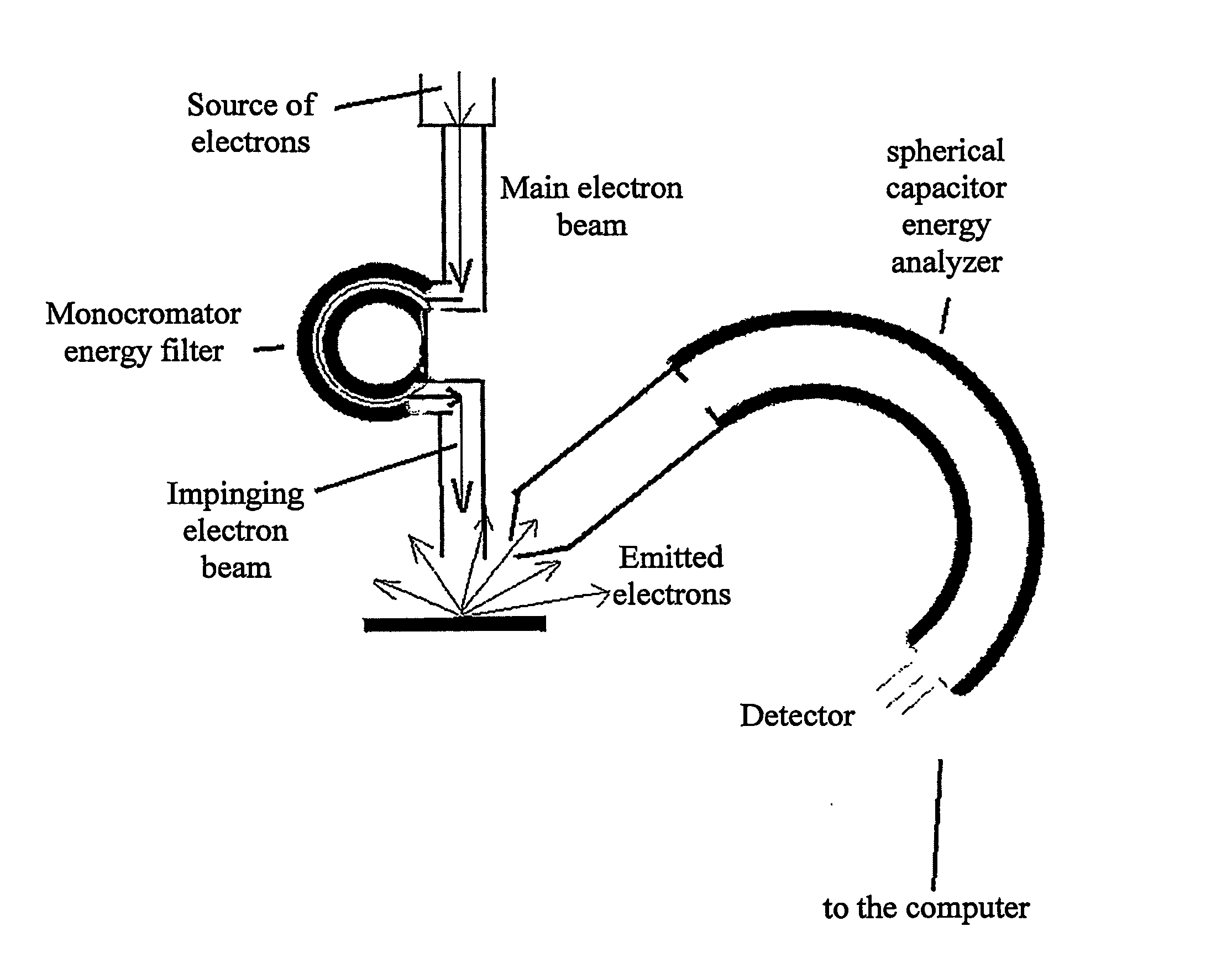
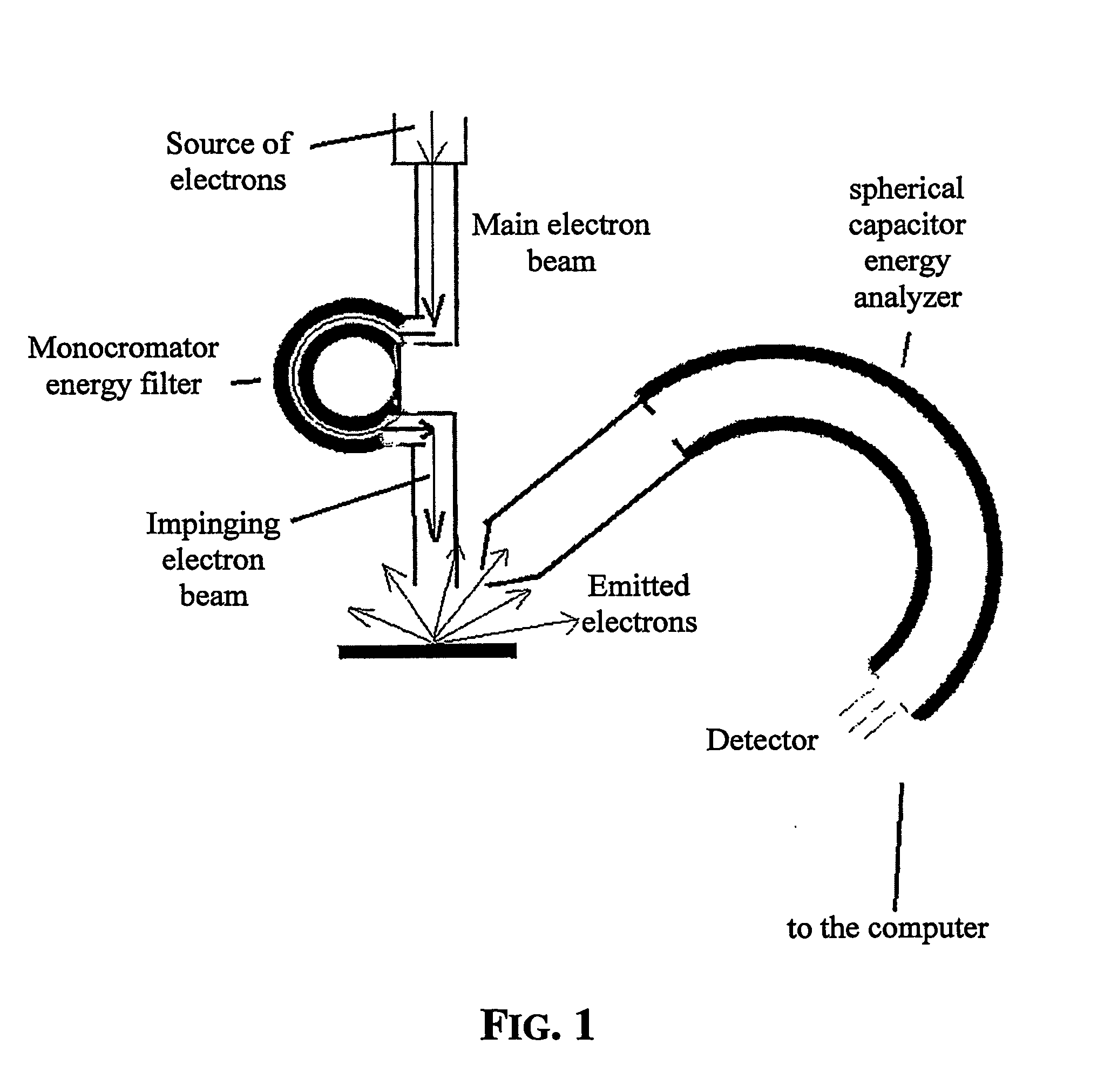
[0025]FIG. 1 is a basic diagram of an electron spectroscope implementing the invention. The field emission electron source is preferably a Schottky emission source. For example, the field emission electron source may be of the type produced by the company FEI of the Philips group or by the Japanese company Denka.

[0026] The monochromator energy filter of the focused electron beam may be any commercially available filter capable of ensuring a maximum energy dispersion of the electrons of the beam exciting the filter of less than 0.2 eV, and more preferably less than 0.1 eV.

[0027] The filtered electron beam is directed on the surface of the sample being analyzed. The irradiated area may have linear dimensions as small as 100 nm, or even less. Of course, scanning a certain area of the sample is done as in any other known focused electron beam system. Analysis of the kinetic energy spectrum of the electrons emitted from the excited area of the sample is carried out with a common spheri...


PUM


Abstract

An electroscope system excites a certain area of a surface of a sample to emit electrons with a characteristic distribution of kinetic energies. The analyzed area of the sample is excited by an electron beam produced by a field emission source. A monochromator energy filter for the electron beam is down-stream of the field emission source. The field emission electron source is preferably a Schottky source, and a monochromator energy filter reduces energy dispersion of the electrons of the electron beam to less than 0.2 eV. Microareas of linear dimensions on the order of ten nanometers may be analyzed while observing them. Information on the chemical state of the detected elements present at the surface of the examined microarea of the sample is gathered.

Description

FIELD OF THE INVENTION [0001] The present invention relates in general to spectroscopy, and more particularly, to a spectroscopic system that analyzes the energy distribution of electrons emitted by a sample suitably excited by irradiation. BACKGROUND OF THE INVENTION [0002] Electron spectroscopy analysis is an important technique for investigating solid materials. Basically, there are two types of spectroscopy systems. Each system has peculiar characteristics and features; namely the Auger system and the XPS (X-ray photoelectron spectroscopy) system. [0003] Both types of systems are based on detecting the kinetic energy of electrons emitted from the surface of the sample subjected to bombardment with electrons, or irradiation with X-rays. The energies of the electrons emitted from the surface of the sample are characteristics of the elements and / or compounds present at the surface of the sample. [0004] The Auger system permits inspections to micro-areas of the sample surface down t...

Claims


Application Information

Patent Timeline
IPC IPC(8): H01J47/00G01N23/227H01J37/05H01J37/256H01J49/08
CPCG01N23/227H01J37/05H01J37/256H01J2237/053H01J2237/2561H01J2237/06316H01J2237/24571H01J2237/2511H01J2237/057
Inventor ALBERICI, STEFANO GIOVANNI
Owner STMICROELECTRONICS SRL
Why Eureka
Try Eureka