Image forming apparatus

a technology of forming apparatus and forming fluid, which is applied in the direction of electrographic process apparatus, instruments, optics, etc., can solve the problems of unsatisfactory increase in material cost, inability to fix multi-color toner images, and much time heed to be spent fixing multi-color toner images, so as to eliminate local variation in equality and avoid splashing and dropping of fixing fluid

Inactive Publication Date: 2007-09-13
SHARP KK
View PDF7 Cites 16 Cited by
  • Summary
  • Abstract
  • Description
  • Claims
  • Application Information

AI Technical Summary

Benefits of technology

[0068] According to the invention, the control unit effects controlling of the rotational driving section in a manner so as to assure the rotation of the applying member that has been separated from the toner image bearing section by the heat-insulating protection member. That is, with the applying member kept at rest in a non-rotating state, the fixing fluid on the surface of the applying member may flow under gravitational force to eventually build up locally. If the applying member is rotated in this state in the absence of the heat-insulating protection member, there arises the possibility of splash and dropping of the buildup of the fixing fluid. In light of this, by rotating the applying member in a closed space, it is possible to avoid splash and dropping of the fixing fluid caused by the rotation of the applying member effected upon the resumption of image formation, and thereby protect the interior of the image forming apparatus against contamination.
[0069] Moreover, even in the presence of the heat-insulating protection member, when left standing for an extended period of time, the applying member may undergo local variation in the proportions of the constituent components in the fixing fluid deposited on its surface. In light of this, by rotating the applying member immediately after the image forming apparatus is turned on and after a lapse of a predetermined time interval following the completion of the previous image formation process, it is possible to eliminate the local variation in equality of the fixing fluid on the surface of the applying member. Accordingly, the fixing fluid layer on the surface of the applying member can be maintained uniform, and thus image irregularity resulting from lack of uniformity in the application of the fixing fluid can be prevented. Hence, high-quality images can be produced with stability for a longer period of time.

Problems solved by technology

Unfortunately, the heat fixing method presents the following disadvantages.
This creates the need to enhance the heat resistance of constituent components, which results in an undesirable increase in material costs.
Secondly, image fixation cannot be effected until a part to be fixed has been heated to a predetermined temperature.
Thirdly, much time heeds to be spent in fixing a multi-color toner image onto a recording medium as compared to the case of fixing a monochromatic toner image.
Moreover, in a case where the percentage of print coverage on an image to be formed is low, no heating operation is carried out to reduce power consumption.
Inconveniently, the generation of wrinkles, curls, or the like is particularly notable in this image forming apparatus, because the water content in the fixing fluid cannot be vaporized readily due to the relatively low fixing temperature set for the fixing means.
Accordingly, this image forming apparatus failed to overcome the drawback associated with the wet fixing method, namely, the generation of wrinkles, curls, or the like in the recording sheet that occurs when the fixing fluid applied to the toner-absent part of the toner image borne on the intermediary transfer belt finds its way into the recording sheet in accompaniment with the image transference and fixation.
Furthermore, a customarily-used fixing fluid is highly volatile.
Therefore, the amount of the fixing fluid on the surface of the applying member becomes uneven, which leads to a failure of applying the fixing fluid to the toner image evenly.
As a result, there arise lack of uniformity in the application of the fixing fluid and thus irregularity in an image obtained.
In this case, the fixing fluid cannot be spread evenly across the groove on the surface of the applying member, in consequence whereof there results lack of uniformity in the application of the fixing fluid to the recoding sheet.
This could lead not only to image irregularity but also to image defects resulting from improper fixation.
Another problem is that the grooves created on the applying member are made uniform in dimension, and thus the amount of the fixing fluid to be applied remains invariant.
Therefore, in a case where the percentage of print coverage on an image to be formed is varied, depending upon the value of the percentage, the amount of the fixing fluid to be applied is so small that fixation ends in failure, or is so large that the occurrence of image flow and generation of wrinkles, curls, or the like induced by the fixing fluid are inevitable.
For example, even if the number of rotation of the applying member is so controlled as to cope with a change in print coverage rate, since the applying member and the end of the opening of the fixing fluid chamber are kept in sliding contact with each other, this construction presents a problem in the provision of long-term durability.
At this time, the surface of the applying member may suffer from scratches, which gives rise to lack of uniformity in the application of the fixing fluid.
Besides, in this construction, since the shutter member is so disposed as to cover the applying member from underneath, the fixing fluid may leak from the gap between the shutter member and the fixing fluid chamber or the applying member.
In this case, the image forming apparatus may be interiorly contaminated with the fixing fluid leakage.

Method used


Image

  • Image forming apparatus
  • Image forming apparatus
  • Image forming apparatus

Examples


first embodiment

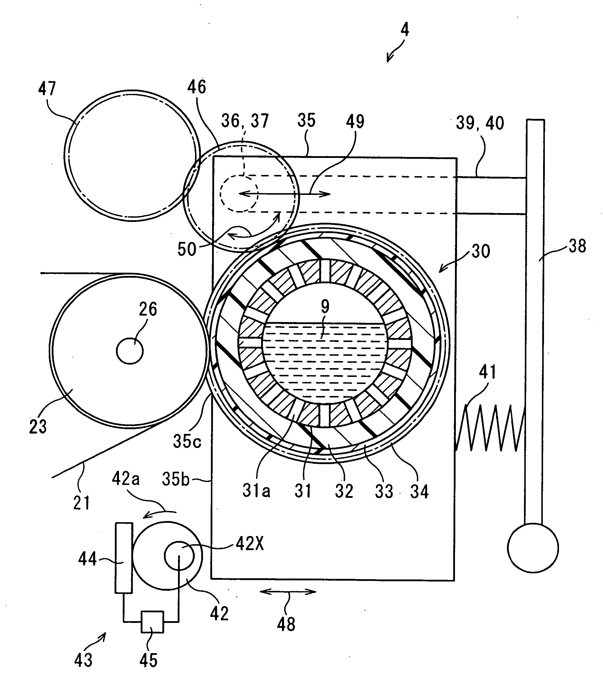
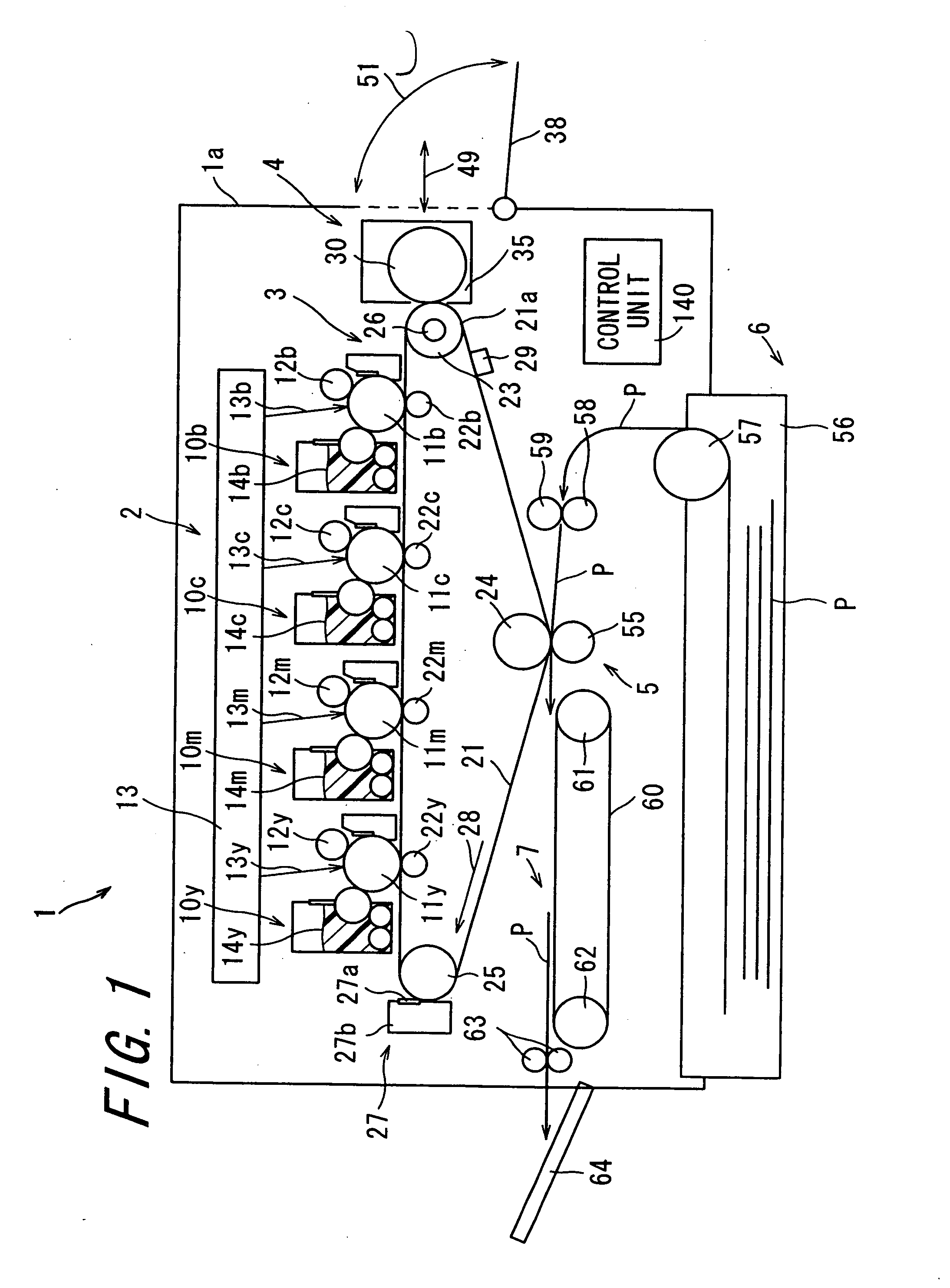
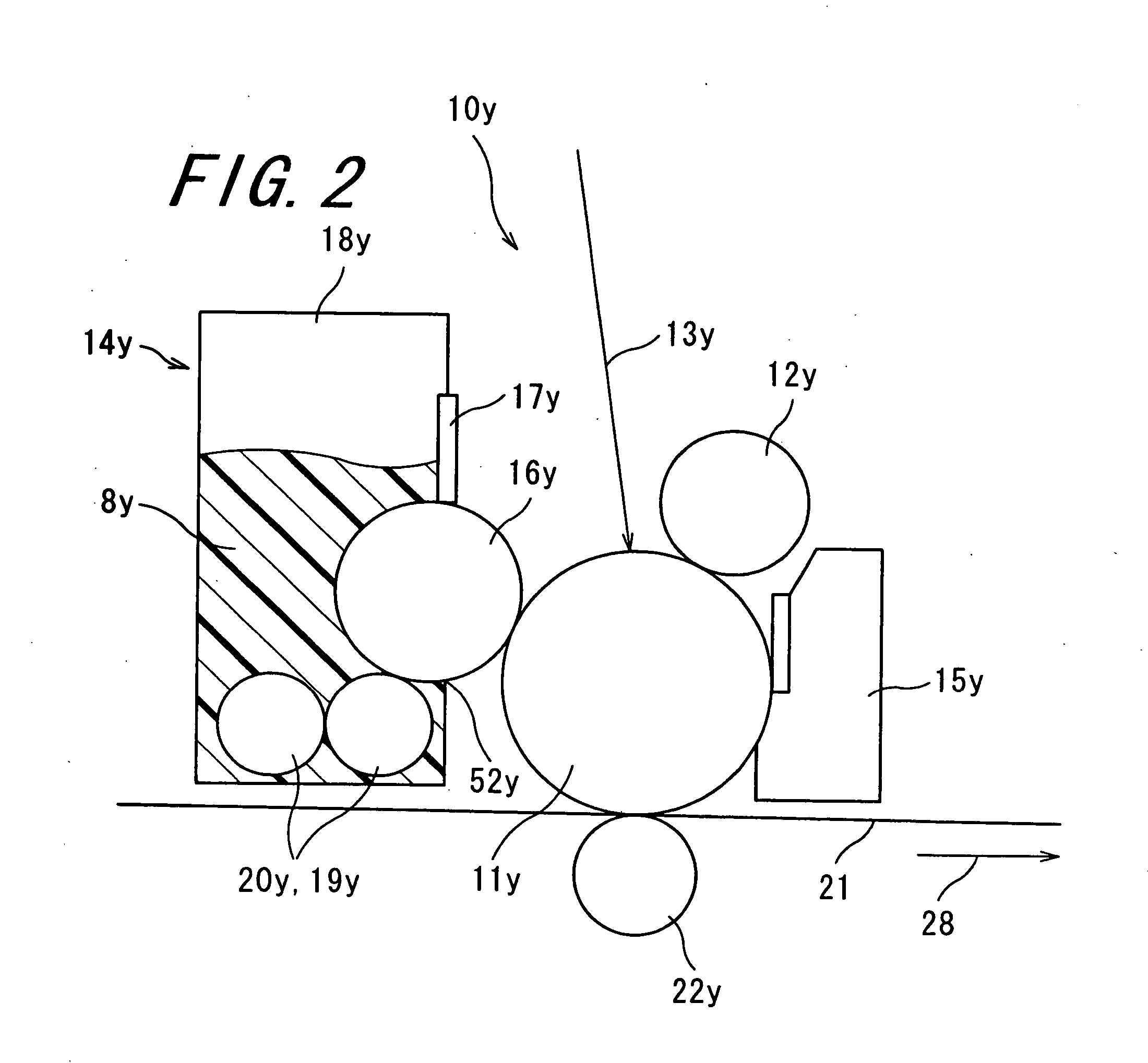
[0091]FIG. 1 is a sectional view schematically showing the constitution of an image forming apparatus 1 implemented according to the invention. FIG. 2 is a sectional view showing the structure of the main portion (a toner image forming section 2 as will be described later) of the image forming apparatus 1 depicted in FIG. 1 in enlarged form. FIG. 3 is a sectional view showing the structure of the main portion (a fixing fluid applying section 4 as will be described later) of the image forming apparatus 1 depicted in FIG. 1 in enlarged form.

[0092] The image forming apparatus 1 is built as a tandem-system electrophotographic image forming apparatus in which toner images of four colors: yellow; magenta; cyan; and black are superimposedly transferred one after another. The image forming apparatus 1 is composed of the toner image forming section 2, intermediary transfer section 3, the fixing fluid applying section 4, transferring and fixing section 5, recording medium supply section 6, an...

second embodiment

[0137]FIG. 10 is a sectional view schematically showing the constitution of an image forming apparatus 95 according to the invention. FIG. 11 is a sectional view schematically showing the structure of the main portion (a fixing fluid applying section 96 and a transferring and fixing section 97) of the image forming apparatus 95 depicted in FIG. 10. FIG. 12 is a view schematically illustrating how the fixing fluid 9 is applied to a toner image borne on a transferring and fixing roller 112 by a coating roller 99. FIG. 13 is a front view of the fixing fluid applying section 96, as viewed in the direction of the transferring and fixing roller 112. FIG. 14 is a sectional view of the fixing fluid applying section 96 taken along the line XIV-XIV of FIG. 13. FIG. 15 is a partial sectional view of the fixing fluid applying section 96 depicted in FIG. 13, as viewed in a direction longitudinally thereof. The image forming apparatus 95 is analogous to the image forming apparatus 1, and therefor...


PUM


Abstract

An image forming apparatus includes a toner-image forming section, an intermediary transfer section including an intermediary transfer belt, a fixing-fluid applying section, a transferring and fixing section, a recording-medium supply section, and an ejection section. The fixing-fluid applying section includes a coating roller, an eccentric cam for moving the coating roller approachably and separably with respect to the intermediary transfer belt, a contact and release detecting section for detecting whether the coating roller is contacted by or away from the intermediary transfer belt, a rotational driving section for rotatably driving the coating roller, and a control unit for controlling the eccentric cam and the rotational driving section.

Description

CROSS-REFERENCE TO RELATED APPLICATION [0001] This application claims priority to Japanese Patent Application No. JP 2006-14407, which was filed on Jan. 23, 2006, the contents of which, are incorporated herein by reference, in their entirety. BACKGROUND OF THE INVENTION [0002] 1. Field of the Invention [0003] The present invention relates to an image forming apparatus. [0004] 2. Description of the Related Art [0005] The adoption of electrophotographic image forming apparatuses as copying machines, printers, facsimile machines, and the like equipment has been widespread. In general, image formation is carried out by an electrophotographic image forming apparatus as follows. As a photoreceptor, the one having formed on its surface a photosensitive layer containing a photoconductive substance is used. After electric charge is applied to the surface of the photoreceptor in such a way that the entire surface is charged evenly, an electrostatic latent image corresponding to specific image...

Claims


Application Information

Patent Timeline
Patent Type & Authority Applications(United States)
IPC IPC(8): G03G15/16
CPCG03G2215/1695G03G15/169
Inventor ASAKURA, KENJIYAMANA, SHINJI
Owner SHARP KK
Why Eureka
Try Eureka