Retaining device for heat sink

a technology of retaining device and heat sink, which is applied in the direction of snap fasteners, semiconductor/solid-state device details, lighting and heating apparatus, etc., can solve the problems of difficult machined shape of combination seats, difficult to form surfaces and two pairs of positioning slots with different levels, and complicated shape of switch elements of retaining devices. , to achieve the effect of simple structure, effective retaining effect and low cos

Inactive Publication Date: 2007-09-13
HUANG PO HUI
View PDF24 Cites 3 Cited by
  • Summary
  • Abstract
  • Description
  • Claims
  • Application Information

AI Technical Summary

Benefits of technology

[0007]It is therefore an object of the invention to provide a retaining device for a heat sink having the simplified structure, the low cost and the effective retaining effect.
[0009]According to the retaining device, the invention has the following advantages.
[0010]First, the elements of the invention are simpler, the cost can be effectively reduced, and the product competitiveness can be enhanced. The control member is the simple flat disk having a control slot, which is simple and may be easily and precisely formed. The two tabs of the retaining piece are symmetrical and the connection seat is the simple base, so the elements have the simple shape and the low cost and may be easily machined.
[0011]Second, the control member of the invention is disposed in the accommodating slot of the connection seat and only has to be rotated unidirectionally. So, the space required by the control member and the size of the control member are smaller than those in the prior art, and the control flow is smoother.
[0012]Third, rotating the control member having the eccentric control slot can retain the retaining piece and the connection seat together or loosen the mounting seat on the heat sink because the radial distances from two ends of the control slot to the center of the control member are different from each other. The pivot only has to be moved in the control slot. The contact surface between the pivot and the inner surface of the control slot only covers the axial thickness section of the disk. So, the contact surface and the friction force are smaller, and the control member can move the connection seat and the retaining piece in a smoother manner.

Problems solved by technology

However, the shape of the switch element of the retaining device is quite complicated.
For example, the guiding bevels with different levels and arced surfaces and two pairs of positioning slots with different levels cannot be easily formed on the circumferential side of the hollow body of the switch element.
In addition, the machined shape of the combination seat is not simple because the combination seat has to be positioned to the retaining piece without rotation.
Also, two sides of the top end of the retaining piece are not symmetrical.
Thus, the cost has to be increased because many elements have complicated structures.
The difficulty in the machining technology is increased and the stable quality cannot be ensured.

Method used


Image

  • Retaining device for heat sink
  • Retaining device for heat sink
  • Retaining device for heat sink

Examples


Embodiment Construction

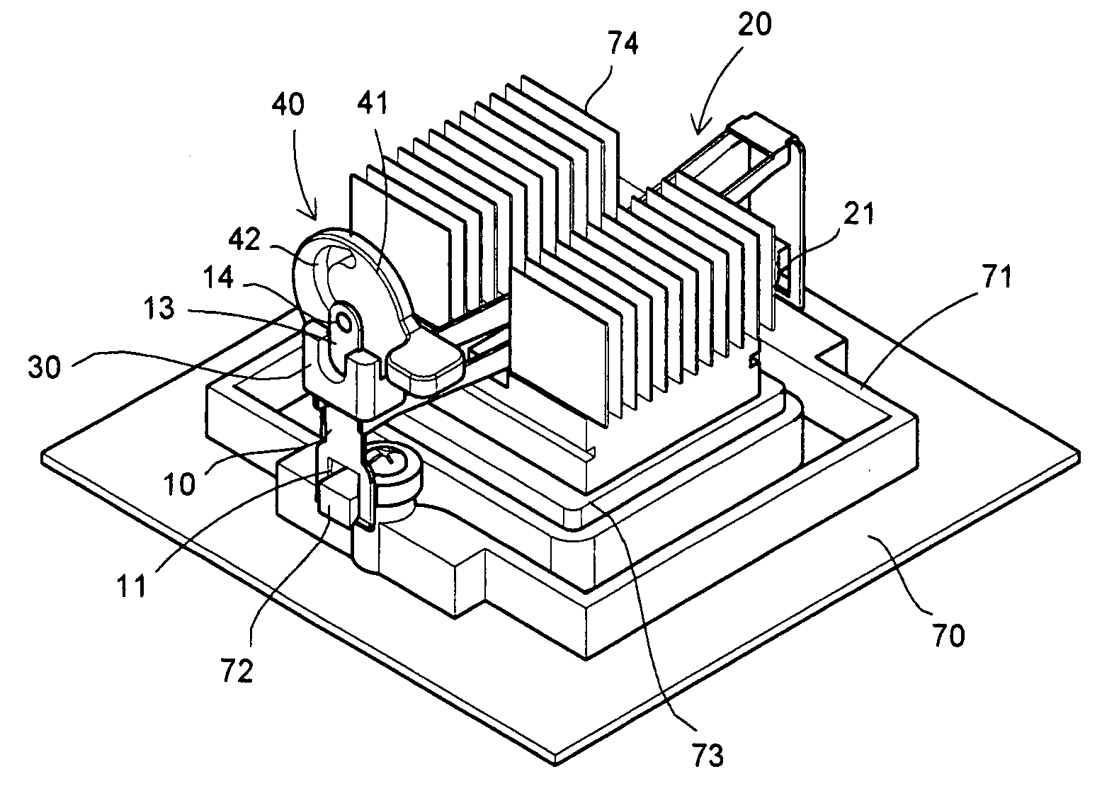
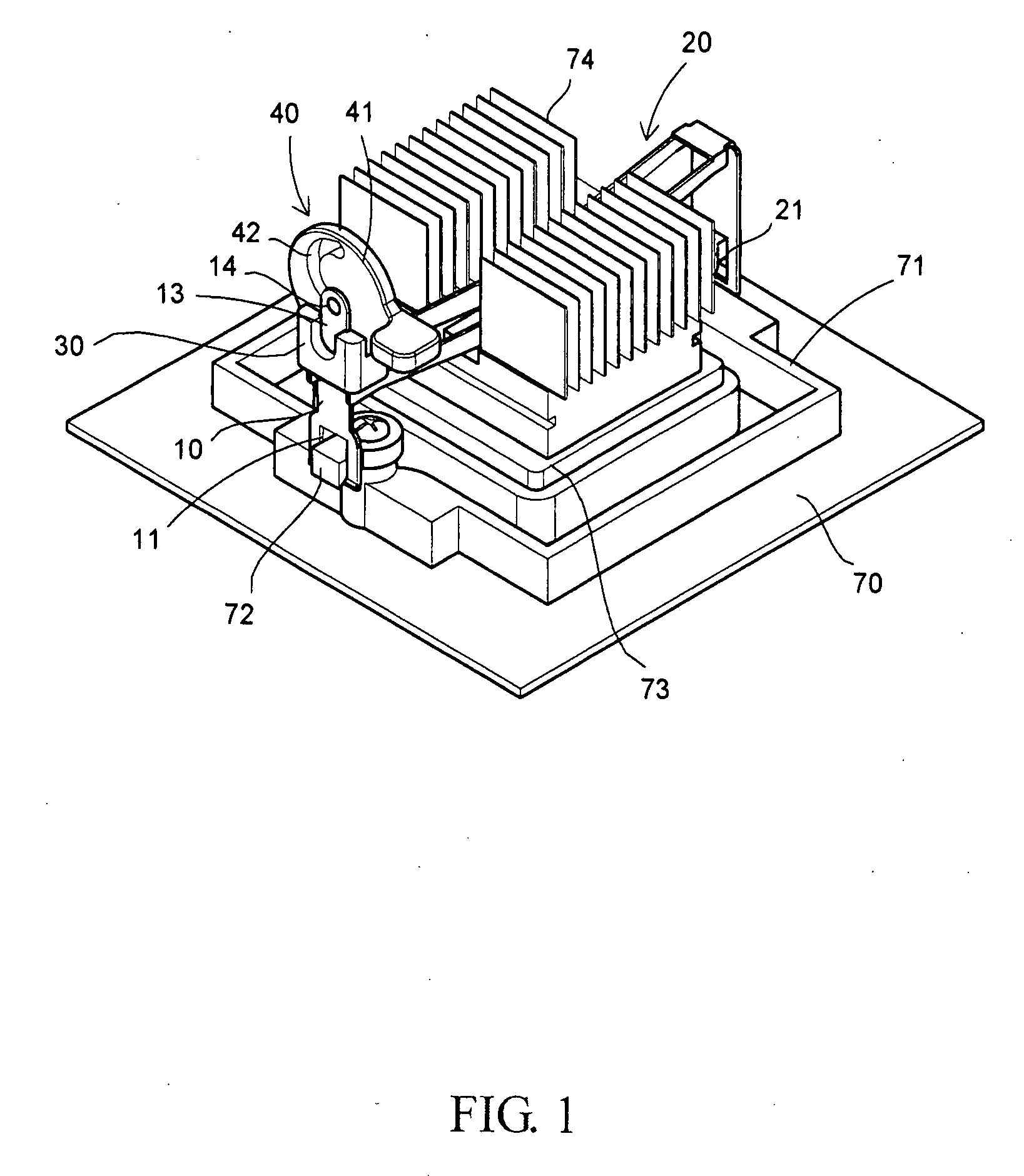
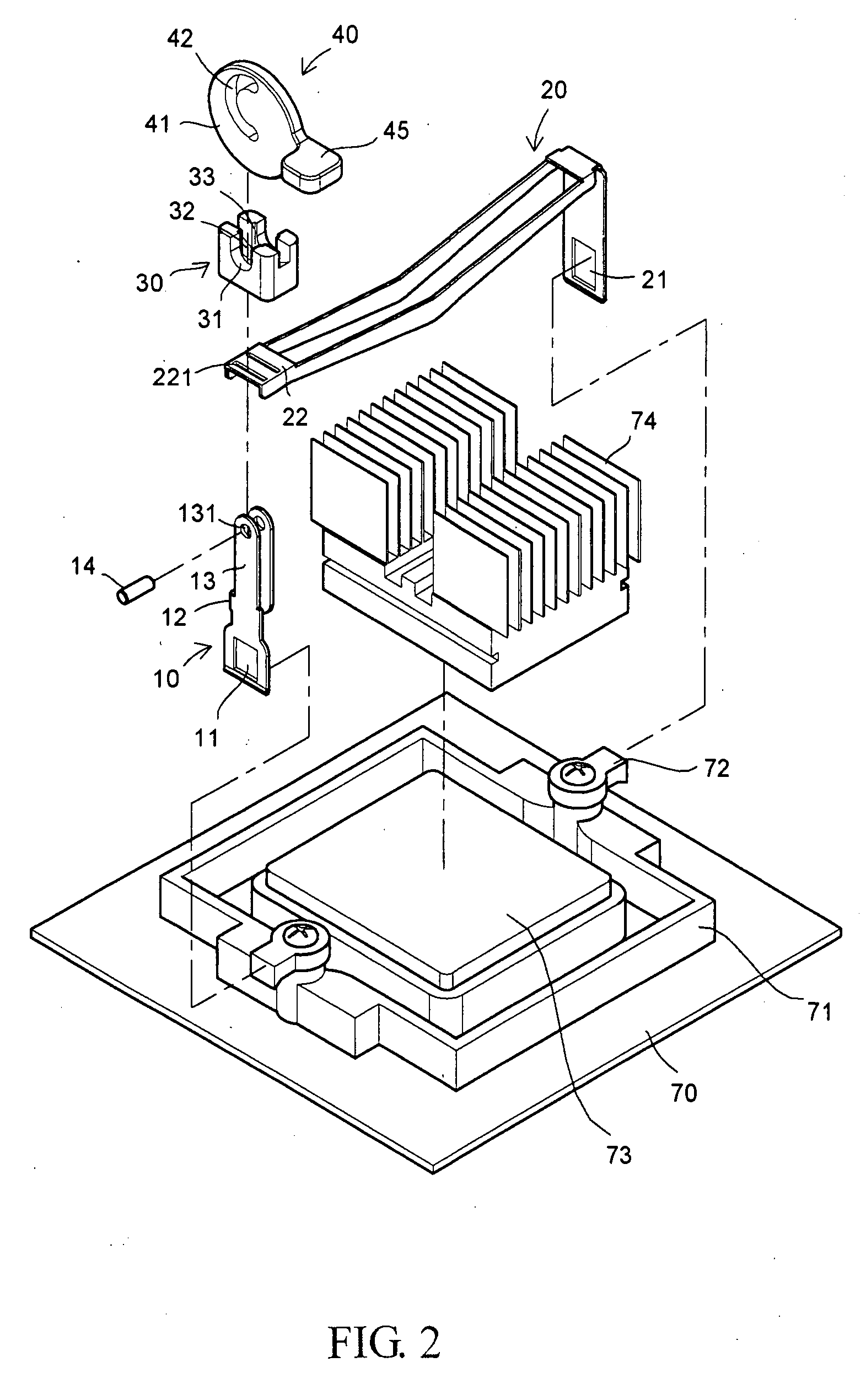
[0023]The invention provides a retaining device for a heat sink, as shown in FIG. 1. A mounting seat 71 is disposed on a mainboard 70. Two sides of the mounting seat 71 are formed with engaging blocks 72, respectively. A heat sink 74 is to be disposed on a central processing unit (CPU) 73. In this invention, the retaining device for positioning the heat sink 74 on the mainboard 70 includes a retaining piece 10, a retaining arm 20, a connection seat 30 and a control member 40, which constitute the retaining device having a simple structure and can effectively retain the heat sink 74 onto the mainboard 70.

[0024]As shown in FIGS. 1 to 3, the retaining piece 10 is formed with a retaining hole 11 at a distal end thereof, and formed with a tab 13 at a top end thereof. One side of the retaining piece 10 laterally extends to form a connection section 12, and the connection section 12 extends upwards to form another tab 13. Thus, two opposite and longitudinal tabs 13 are formed, and the tabs...


PUM


Abstract

A retaining device for a heat sink includes a retaining piece, a retaining arm, a connection seat and a control member. The retaining piece has one end formed with a retaining hole and a top end formed with two tabs. The retaining arm has a vertical surface formed with a retaining hole. The tabs penetrate through the retaining arm and then the connection seat having an accommodating slot. The control member has a disk and a handle connected thereto. The disk in the accommodating slot has a hollow eccentric control slot. A pivot mounted to the tabs may slide in the control slot. The control member is rotated to move the pivot, which causes a relative movement between the retaining piece and the connection seat so that the retaining hole retains a mounting seat of the heat sink while the retaining arm tightly presses against the heat sink.

Description

BACKGROUND OF THE INVENTION[0001]1. Field of the Invention[0002]The invention relates to a retaining device for a heat sink and to the retaining and positioning technology for a central processing unit and the heat sink applied to the heat dissipating field of a digital data processing device, and more particularly to a retaining device for a heat sink capable of simplifying a positioning device of the invention and ensuring the good retaining effect.[0003]2. Description of the Related Art[0004]A central processing unit (CPU) is a heart for a digital processing device. The CPU generates heat as it is operating. In order to dissipate the heat of the CPU and thus to prevent the heat from influencing the operating efficiency of the CPU, a retaining device is provided to fix a fin-like heat sink to the CPU. As shown in FIG. 8, the retaining device includes a retaining arm 75, a retaining piece 80, a combination seat 85 and a switch element 90. The retaining arm 75 has one end formed wit...

Claims


Application Information

Patent Timeline
Patent Type & Authority Applications(United States)
IPC IPC(8): H05K1/00A44B99/00
CPCH01L23/4093H01L2924/0002Y10T24/44017H01L2924/00
Inventor HUANG, PO-HUI
Owner HUANG PO HUI
Why Eureka
Try Eureka