Heat exchanger and refrigeration cycle device using the same

a technology of heat exchanger and cycle device, which is applied in the field of heat exchanger, can solve the problems of increasing thermal conduction loss, difficult to use such a structure of heat exchanger, and inability to use refrigerant types, so as to improve heat exchanger pressure resistance, improve heat exchanger performance, and reduce heat loss at the inl

Inactive Publication Date: 2007-09-20
PANASONIC INTELLECTUAL PROPERTY MANAGEMENT CO LTD
View PDF7 Cites 13 Cited by
  • Summary
  • Abstract
  • Description
  • Claims
  • Application Information

AI Technical Summary

Benefits of technology

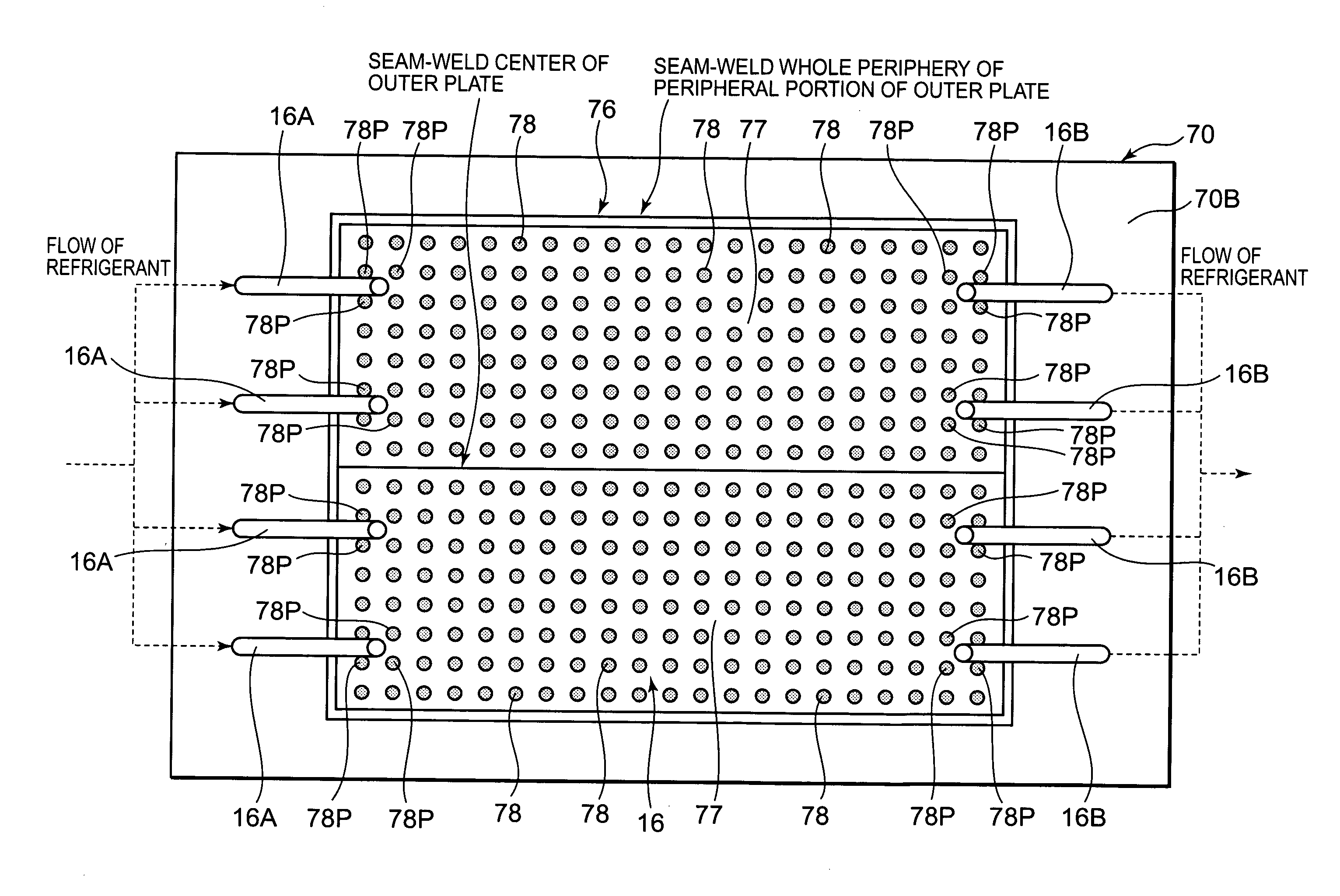
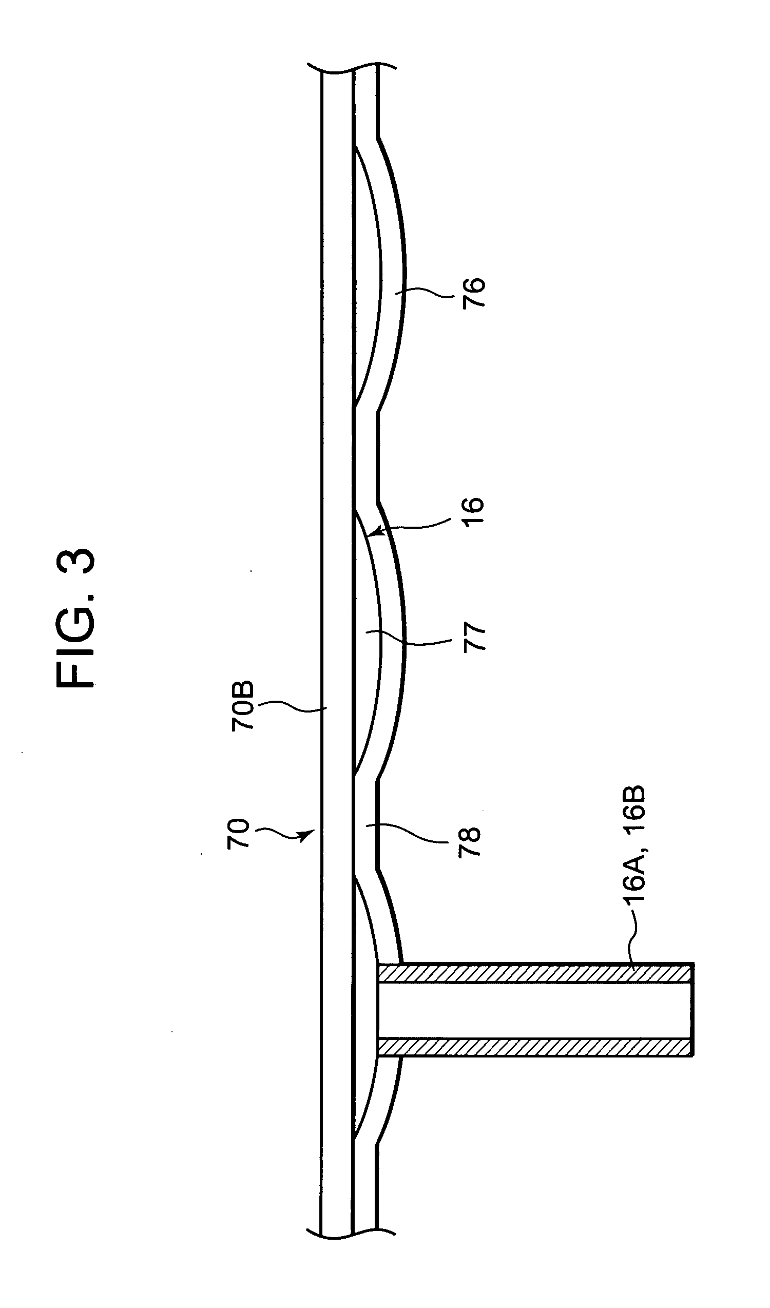
[0012] According to the present invention, the heat exchanger comprises a pair of plate materials. The whole periphery of the peripheral portion of at least one of the plate materials is secured to the other plate material to constitute the sealed refrigerant passage space between the plate materials. Moreover, the portion of the one plate material other than the peripheral portion is provided with the plurality of secured inner portions which are secured at the predetermined intervals to the other plate material. Therefore, for example, after the whole periphery of the peripheral portion of the one plate material is secured to the other plate material, a pressure is applied between the plate materials. In consequence, the refrigerant passage space is swelled and formed between the plate materials. Therefore, where a pressure resistance of the heat exchanger is secured, a thermal performance of the refrigerant can be improved.
[0013] Moreover, since the plurality of refrigerant inlet tubes and refrigerant outlet tubes are attached so as to communicate with the refrigerant passage space, pressure losses of the refrigerant at an inlet and an outlet of the heat exchanger can be reduced while securing the pressure resistance of portions of the heat exchanger bonded to the refrigerant inlet tubes and the refrigerant outlet tubes.
[0014] Furthermore, when the secured inner portions are arranged at the predetermined intervals in the checkered form or the zigzag form, the pressure resistance of the heat exchanger can be improved without increasing thicknesses of the one plate material and the other plate material.
[0015] In addition, according to the present invention, the refrigerant inlet tubes communicate with the refrigerant passage space in the center of the refrigerant passage space, and the refrigerant outlet tubes communicate with the refrigerant passage space in the peripheral portion of the refrigerant passage space. Therefore, since the refrigerant entering the refrigerant passage space from the center flows so as to spread to the peripheral portion, the refrigerant obtains a satisfactory diversion property. Stagnation of the refrigerant in the heat exchanger can be prevented or eliminated as much as possible.
[0016] Since the heat exchanger of the present invention has an excellent pressure resistance, the heat exchanger can be used as the evaporator of the refrigeration cycle device in which carbon dioxide is introduced as the refrigerant. In consequence, it is possible to improve a performance of the refrigeration cycle device in which the carbon dioxide refrigerant is used.

Problems solved by technology

However, in recent years, this type of refrigerant cannot be used owing to global environment problems such as prevention of ozone layer destruction and prevention of global warming, and attempts to use carbon dioxide as the refrigerant instead of the fluorocarbon-based refrigerant have been made.
However, to bear such a high pressure of the carbon dioxide refrigerant, a thickness of each member constituting the heat exchanger needs to be increased, but this causes a problem of an increasing thermal conduction loss.
Especially, in a case where the heat exchanger is constituted of an evaporator to cool an object to be cooled stored in a cooling vessel from the outside of the cooling vessel, it has been difficult for such a structure of the heat exchanger to bear the high pressure of the carbon dioxide refrigerant and secure the high thermal performance.
That is, when the member constituting the evaporator is thickened so as to bear the high pressure of the carbon dioxide refrigerant, the thermal conduction loss further increases.
As a result, a problem occurs that the thermal performance remarkably deteriorates as compared with the evaporator in which the conventional refrigerant is used.
Therefore, such remarkable deterioration of the thermal performance cannot be avoided.

Method used


Image

  • Heat exchanger and refrigeration cycle device using the same
  • Heat exchanger and refrigeration cycle device using the same
  • Heat exchanger and refrigeration cycle device using the same

Examples


embodiment 1

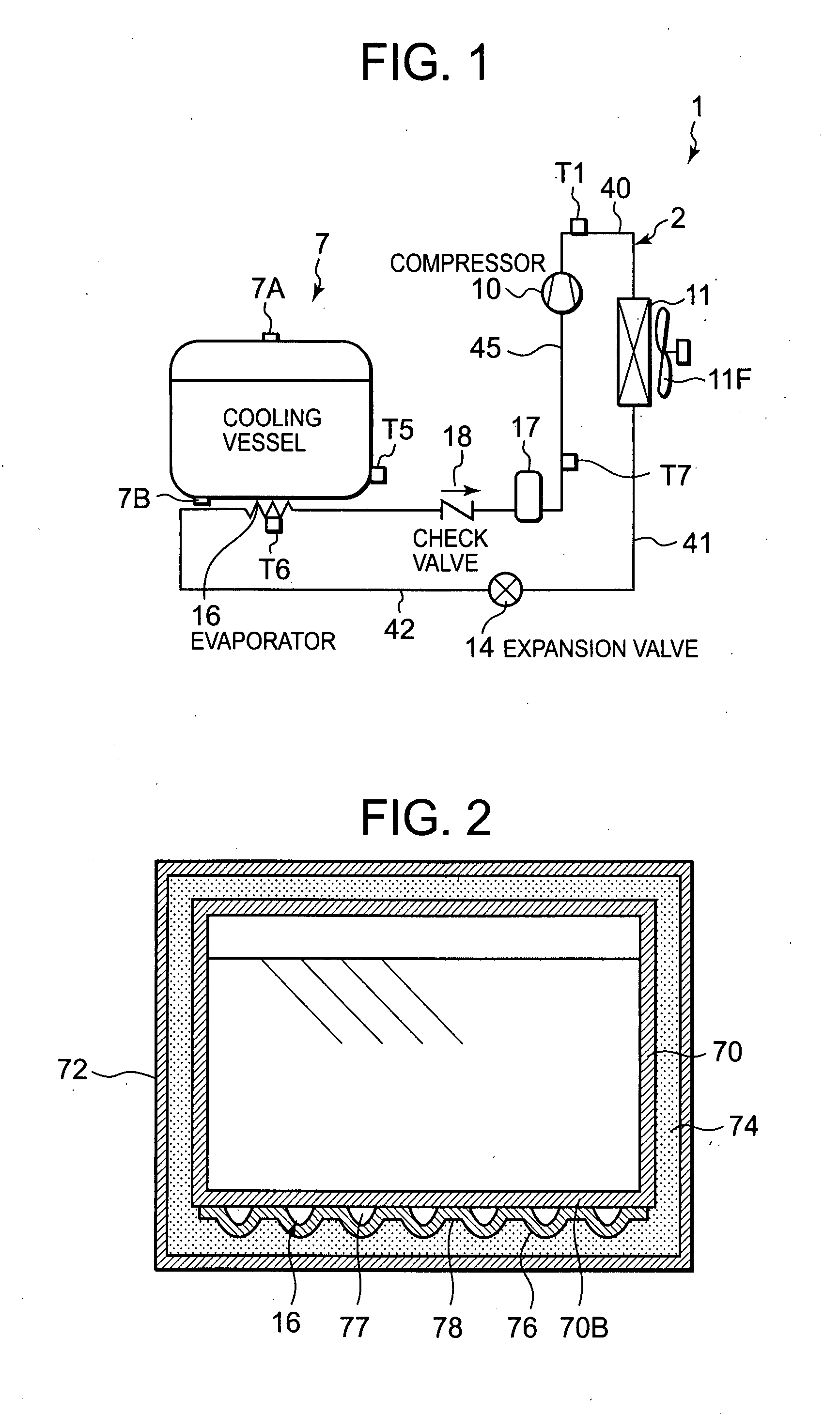
[0025] A refrigeration cycle device of the present embodiment is one example applied to a device which cools and insulates milk immediately after drawn until the milk is shipped. FIG. 1 is a schematic constitution diagram of the refrigeration cycle device of one embodiment to which the present invention is applied. A refrigeration cycle device 1 of the present embodiment is provided with a refrigerant circuit 2 constituted by connecting a compressor 10, a condenser (condensing heat exchanger or gas cooler or gas cooling heat exchanger) 11, an expansion valve 14 as a throttling means and an evaporator 16 in an annular form via pipes so as to form a closed circuit. That is, a high-pressure refrigerant pipe 40 connected to the compressor 10 on a discharge side is connected to an inlet of the condenser 11. The condenser 11 is a heat exchanger which performs heat exchange between a refrigerant and a heat medium to release heat of the refrigerant to the heat medium. It is assumed in the p...


PUM


Abstract

An object is to improve a pressure resistance and a thermal performance of a heat exchanger and to provide the heat exchanger suitable for use in a refrigeration cycle device in which carbon dioxide is used as a refrigerant. The evaporator (the heat exchanger) includes a pair of plate materials, the whole periphery of a peripheral portion of an outer plate as at least one of the plate materials is secured to the other plate material constituting a bottom surface of an inner tank to constitute a sealed refrigerant passage space between the plate materials, a portion of the outer plate other than the peripheral portion is provided with a plurality of secured inner portions which are secured at predetermined intervals to the bottom surface, and a plurality of refrigerant inlet tubes and refrigerant outlet tubes are attached so as to communicate with the refrigerant passage space.

Description

BACKGROUND OF THE INVENTION [0001] The present invention relates to a heat exchanger. The present invention more particularly relates to a heat exchanger for use in a refrigeration cycle (vapor-compression refrigeration cycle) device in which a refrigerant circuit including a compressor, a condenser (or gas cooler or condensing heat exchanger or gas cooling heat exchanger), a throttling means and an evaporator is constituted and in which carbon dioxide is introduced as a refrigerant, and a refrigeration cycle device using the heat exchanger. [0002] Heretofore, in a refrigeration cycle device in which a refrigerant circuit including a compressor, a condenser, a throttling means and an evaporator is constituted, a fluorocarbon-based refrigerant has broadly been used. However, in recent years, this type of refrigerant cannot be used owing to global environment problems such as prevention of ozone layer destruction and prevention of global warming, and attempts to use carbon dioxide as ...

Claims


Application Information

Patent Timeline
Patent Type & Authority Applications(United States)
IPC IPC(8): F28F3/14F25B1/00F25B39/02
CPCF25B9/008F25B39/022F28F3/14F28F3/12F25B2309/061
Inventor OTAKE, MASAHISASATO, KOJIMUKAIYAMA, HIROSHIKIDO, KIYOTAKA
Owner PANASONIC INTELLECTUAL PROPERTY MANAGEMENT CO LTD
Why Eureka
Try Eureka