
Pellet stove

a technology of pellet stoves and stoves, applied in the field of system and method of heating buildings, can solve the problems of high noise, limited user interface, and limited work options of users in cleaning and maintenance operations, and achieve the effect of less choice for users and high nois

Inactive Publication Date: 2007-09-20
HNI TECH INC
View PDF11 Cites 7 Cited by
  • Summary
  • Abstract
  • Description
  • Claims
  • Application Information

AI Technical Summary

Benefits of technology

The present invention relates to a system and method for controlling a pellet stove. The system includes a firepot assembly with a combustion enclosure and a bottom plate that can be opened and closed. The firepot assembly has a bottom opening and a top opening, and a bottom plate that can be moved between a closed position and an open position. The system also includes a controller that can activate the motor to move the bottom plate between the open and closed positions. The firebox includes thermally conductive airfoils that absorb heat from the combustion site and a convection blower to circulate air. The system also includes a wall control unit and a stove control unit that can automatically control fuel feed rate, ignition, convection blower, combustion blower, and firepot cleaning based on user settings. The system can also receive information about the fuel type and adjust the cleaning frequency accordingly. The technical effects of the invention include improved heating efficiency, control over combustion process, and reduced emissions.

Problems solved by technology

However, current pellet stoves often generate high levels of noise due to noisy blowers and / or turbulent flow of blown air through pellet stove components.
Current pellet stoves often feature limited user interfaces and limited automated controls, which may lead to more work and less choice for the user in cleaning and maintenance operations, for example.
Current pellet stoves can often be expensive or complicated to manufacture, they often run at a relatively low efficiency, and may often be unable to burn low grade fuel or one hundred percent corn fuel, for example.

Method used


Image

  • Pellet stove
  • Pellet stove
  • Pellet stove

Examples


Embodiment Construction

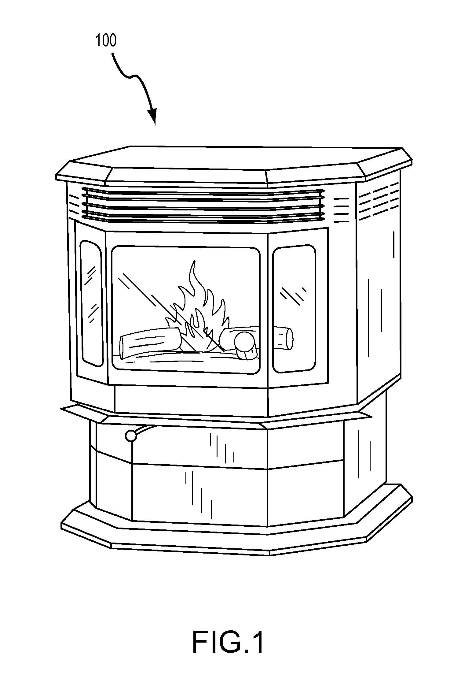
[0057] An exemplary pellet stove 100 is illustrated in FIG. 1. Embodiments of pellet stoves in accordance with the present invention provide greater power efficiency than conventional pellet stoves, enable a user to set a wider range of parameters than in the past, and provide automated features for stove cleaning, ignition, temperature control, and blower control, based on parameters such as, for example, fuel type. Embodiments of pellet stoves described herein are able to burn a wider variety of types of biomass solid fuels, including without limitation: corn, wood pellets, cherry pits, nut shells, sunflower seeds, and pea pellets. Advantageously, pellet stoves according to embodiments of the present invention can automatically adapt various functions based on the type of fuel, and other user preset parameters. In addition, assembly of pellet stoves and / or components of pellet stoves is made easier by unique component attributes, such as a single piece fuel hopper, a rail-based cl...


PUM


Abstract

According to embodiments of the present invention, a pellet stove includes a firepot assembly with a bottom plate slideable along rails to move between a closed position during combustion in the firepot and an open position during ash removal. According to other embodiments, a firebox or combustion enclosure includes a plurality of airfoils formed on the inner and outer surfaces of the enclosure to facilitate heat exchange between exhaust gases flowing across the inner surface of the enclosure and air blown across the outer surface of the enclosure. According to some embodiments, the airfoils and enclosure are of integral unibody construction. According to yet other embodiments, a user sets parameters via a wall control unit, and a stove control unit receives the parameters and automatically controls fuel feed rate, ignition, convection blower, combustion blower, and / or firepot cleaning based on the one or more parameters.

Description

CROSS-REFERENCE TO RELATED APPLICATIONS [0001] This application claims the benefit of U.S. Provisional Patent Application Ser. No. 60 / 780,433, filed on Mar. 8, 2006, and entitled, “Pellet Stove,” the contents of which are incorporated herein by reference in their entirety for all purposes.TECHNICAL FIELD [0002] Embodiments of the present invention relate generally to systems and methods for heating buildings, and more specifically to pellet stove design and control. BACKGROUND [0003] A pellet stove is a type of biofuel stove that burns biomass in the form of pellets to generate heat. Pellet stoves can burn corn kernels, wood pellets, cherry pits, and other types of biomass solid fuel. Pellet stoves became popular during the oil shortages of the 1970s. Over time, pellet stoves have become more sophisticated, and more aesthetically pleasing. Most stoves are now quite attractive, and are often used in homes. Commercial models are available, which can heat large buildings or generate el...

Claims


Application Information

Patent Timeline
Patent Type & Authority Applications(United States)
IPC IPC(8): F24B1/18F24B1/199
CPCF23H15/00F23M2900/13003F23N5/00F23N5/203F24B7/025F24B1/024F24B1/026F24B1/028F23N2039/02F24B1/195F23N2239/02
Inventor MCCORMICK, COLIN J.HENRY, DANIEL S.WICKS, MATTHEWTAYLOR, GORDON E.
Owner HNI TECH INC
Learn More