Portable Wireless Device
a wireless device and portable technology, applied in the direction of polarisation/directional diversity, resonant antennas, substantially flat resonant elements, etc., can solve the problems of user time and communication cost, difficult to realize high speed transmission in downlink communication, etc., to improve reception performance, improve antenna directivity, and high antenna radiation efficiency
- Summary
- Abstract
- Description
- Claims
- Application Information
AI Technical Summary
Benefits of technology
Problems solved by technology
Method used
Image
Examples
embodiment 1
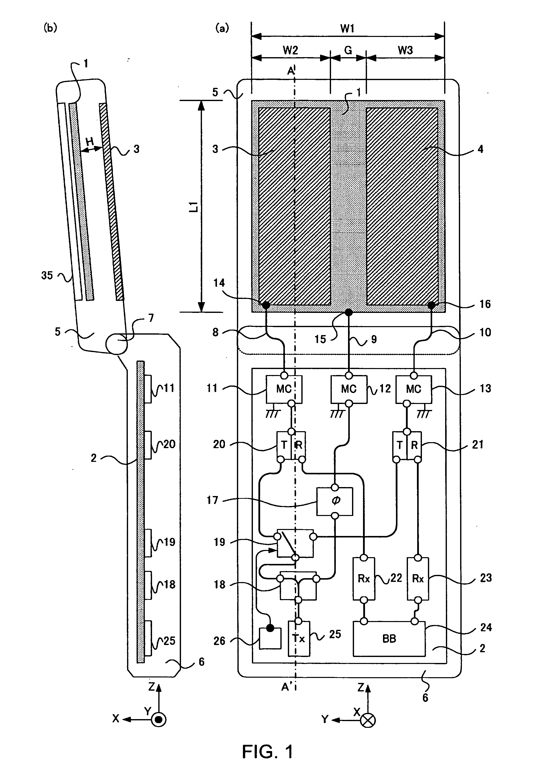
[0031]FIG. 1 is a configuration diagram of a foldable mobile phone of Embodiment 1 of the present invention, and FIG. 1(a) is a back perspective view of the foldable mobile phone when viewed from the backside and FIG. 1(b) is an A-A′ section view in FIG. 1(a). In other words, FIG. 1 shows a front view and a side view of a state in which the mobile phone having a foldable structure is opened to use (hereinafter, referred to an “open state”). The foldable mobile phone has a configuration including upper case 5, lower case 6, hinge section 7, flat conductor 1 (first antenna element), flat conductor 3 (second antenna element), flat conductor 4 (third antenna element), ground plate 2, and display section 35. In the description below, the foldable mobile phone may be simply referred to as a “mobile phone” in some cases.
[0032] Upper case 5 corresponding to the upper housing and lower case 6 corresponding to the lower housing are made of resin that is an insulator, and, in general, upper c...
embodiment 2
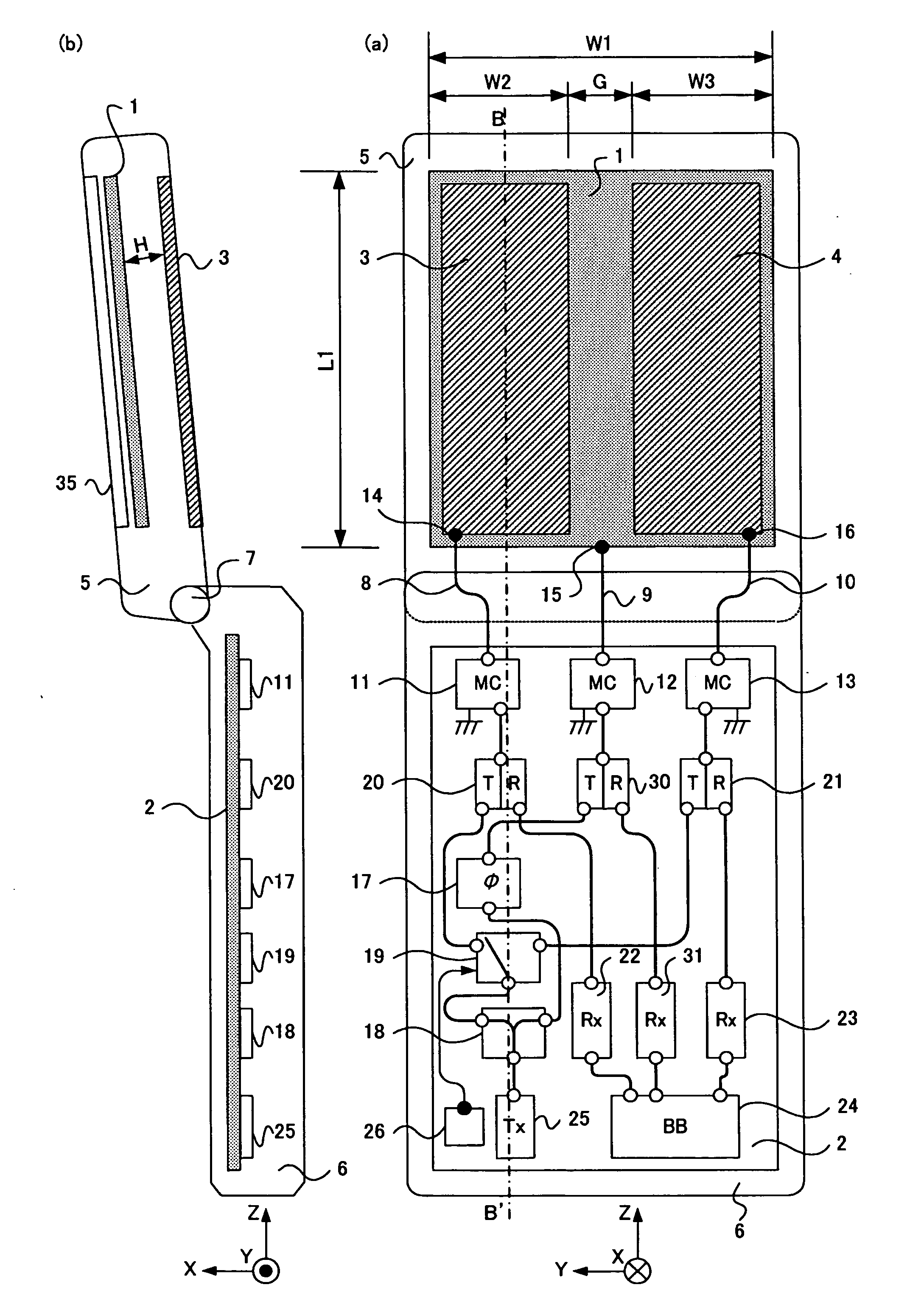
[0053]FIG. 6 is a configuration diagram of a foldable mobile phone in embodiment 2 of the present invention; FIG. 6(a) is a back perspective view when the foldable mobile phone is viewed from the backside; and FIG. 6(b) is a B-B′ section view in FIG. 6(a). The mobile phone shown in FIG. 6 is obtained by adding a duplexer 30 to the system of flat conductor 1 and by further adding a reception circuit (reception section) 31 to the reception system of this duplexer 30, compared to the mobile phone shown in FIG. 1. Other components are the same as in FIG. 1 and are assigned the same codes. Therefore, the duplicated explanation will be omitted.
[0054] In FIG. 6, a high frequency signal is distributed from transmission circuit 25 by power distributor 18, and one of the distributed signals is fed to flat conductor 1 from matching circuit 12 via phase shifter 17 and duplexer 30. The other is fed to flat conductor 3 from one contact of high frequency switch 19 via duplexer 20 and matching cir...
embodiment 3
[0059]FIG. 7 is a configuration diagram of a foldable mobile phone of Embodiment 3 of the present invention; FIG. 7(a) is a back perspective view when the foldable mobile phone is viewed from the backside; and FIG. 7(b) is a C-C′ section view in FIG. 7(a). The mobile phone shown in FIG. 7 is obtained by deleting high frequency switch 19, power distributor 18, and phase shifter 17 from the mobile phone shown in FIG. 6 and newly adding power distributor 40 for distributing a signal to three systems, phase shifter 41, and phase shifter 42. Other components are the same as in FIG. 6 and are assigned the same codes. Therefore, the duplicated explanation of the mobile phone shown in FIG. 1 and FIG. 6 will be omitted.
[0060] In FIG. 7, in the case of the transmission system, a high frequency signal is distributed to three systems from transmission circuit 25 by power distributor 40 and the first system is fed to flat conductor 3 from matching circuit 11 via phase shifter 41 and duplexer 20...
PUM
 Abstract
Description
Claims
Application Information
 - R&D
- Intellectual Property
- Life Sciences
- Materials
- Tech Scout
- Unparalleled Data Quality
- Higher Quality Content
- 60% Fewer Hallucinations
Browse by: Latest US Patents, China's latest patents, Technical Efficacy Thesaurus, Application Domain, Technology Topic, Popular Technical Reports.
© 2025 PatSnap. All rights reserved.Legal|Privacy policy|Modern Slavery Act Transparency Statement|Sitemap|About US| Contact US: help@patsnap.com


