Perpendicular Magnetic Recording Medium Using Soft Magnetic Layer Which Suppresses Noise Generation, And Perpendicular Magnetic Recording Apparatus Therewith

a perpendicular magnetic recording and soft magnetic layer technology, applied in the field of magnetic recording mediums, can solve the problems of large noise generated by the soft magnetic layer of the perpendicular two-layer medium, particularly the noise resulting from the magnetic wall, and difficult to suppress the noise generated by the soft magnetic layer, so as to reduce noise, suppress the magnetic anisotropy, and promote the effect of magnetic flux leakag

Inactive Publication Date: 2007-09-20
KK TOSHIBA +1
View PDF3 Cites 14 Cited by
  • Summary
  • Abstract
  • Description
  • Claims
  • Application Information

AI Technical Summary

Benefits of technology

[0114] In general, the soft magnetic layer of the perpendicular magnetic recording medium forms a part of a magnetic path of the magnetic flux generated from the magnetic head in writing, whereas in reading, the same soft magnetic layer serves as a promoter for promoting the magnetic flux leakage from the magnetic recording layer.
[0115] Heretofore, it is thought that the soft magnetic layer is preferably thick and the coercive force is preferably small, in order to fully exert the effect of magnetic flux.
[0116] Moreover, it is thought that it is more desirable to suppress the magnetic anisotropy, in order to prevent the fine magnetic region which causes a noise in the soft magnetic layer from being formed.
[0117] In addition, because the magnetic wall formation will advance by a formation of a flowing-back magnetic region when the magnetostatic energy of the soft magnetic layer is large, heretofore, it is generally thought that it is desirable to suppress the magnetostatic energy in order to reduce noise.
[0118] However, the inventor of the present invention researched thoroughly and discovered that in the magnetic recording medium having the characteristics which have been thought to be desirable, it becomes easy to generate magnetic walls which roughly divides the soft magnetic layer entirely into a plurality of regions.
[0119] In the magnetic recording medium of the present invention, thickness is less than 100 μm, the soft magnetic layer has the magnetic anisotropy in a surface direction, and the product Bs·Hc of the saturation magnetic flux density Bs and the coercive force Hc is not less than 79 T·A / m (10 kG·Oe).

Problems solved by technology

However, there is a problem in the perpendicular two-layer medium in that the noise resulting from the soft magnetic layer of the perpendicular two-layer medium, particularly the noise resulting from a magnetic wall, is large.
However, in this magnetic recording medium, the magnetic wall which divides the entire soft magnetic layer into a plurality of regions is easily generated, and hence it was difficult to suppress the noise which is generated from the soft magnetic layer.
However, in this magnetic recording medium, the magnetic flux emitted from the soft magnetic layer differs in radial directions, and there is a problem in that that characteristic becomes uneven.
Moreover, the stability of the single magnetic region structure deteriorates, such that generation of noise could not be suppressed sufficiently.
As the situation stands, it is difficult to sufficiently suppress the noise which is generated from the soft magnetic layer in such a magnetic recording medium.

Method used


Image

  • Perpendicular Magnetic Recording Medium Using Soft Magnetic Layer Which Suppresses Noise Generation, And Perpendicular Magnetic Recording Apparatus Therewith
  • Perpendicular Magnetic Recording Medium Using Soft Magnetic Layer Which Suppresses Noise Generation, And Perpendicular Magnetic Recording Apparatus Therewith
  • Perpendicular Magnetic Recording Medium Using Soft Magnetic Layer Which Suppresses Noise Generation, And Perpendicular Magnetic Recording Apparatus Therewith

Examples


working examples

Working Example 1

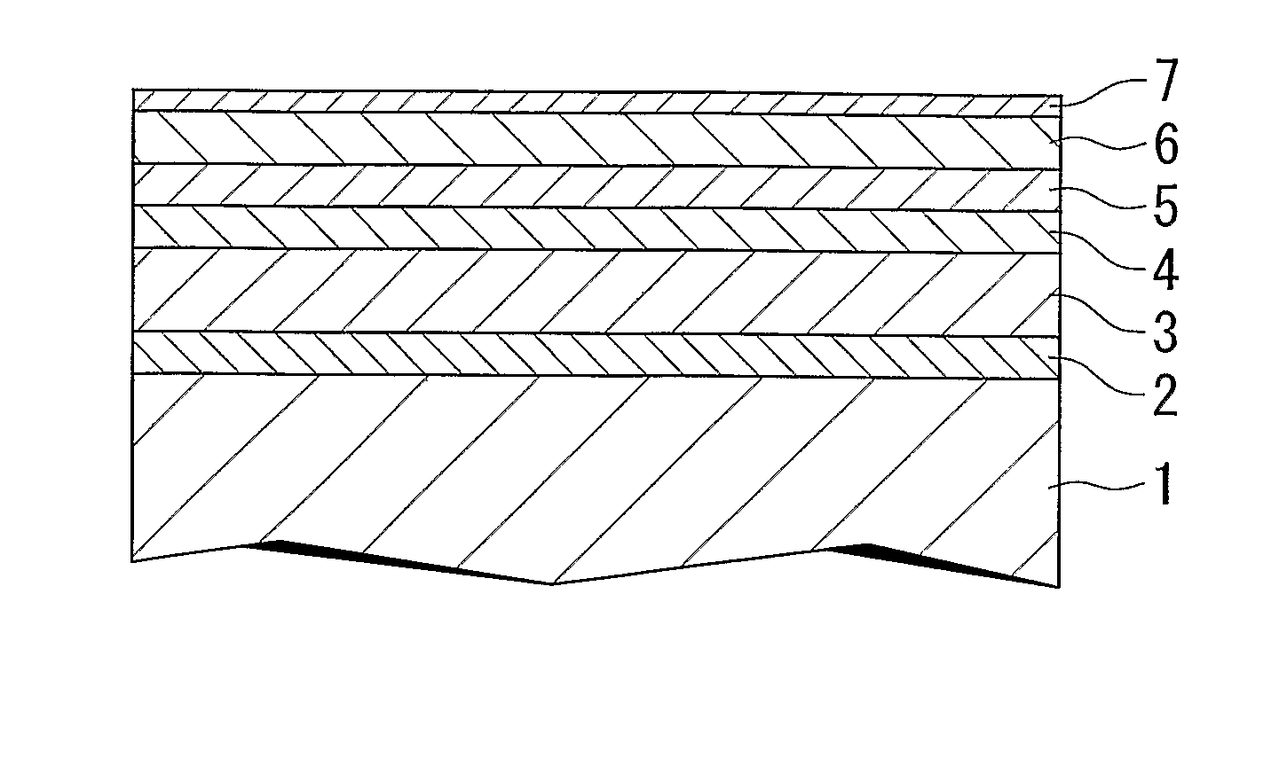
[0133] The magnetic recording medium shown in FIG. 1 was produced as shown below.

[0134] In the production process mentioned below, Ar gas was used as sputtering gas in a sputtering method using a chamber in which the degree of vacuum was set to be not higher than 3×10⁻⁵ Pa.

[0135] A hard magnetic layer 2 which has the magnetic anisotropy in a surface direction is formed on the substrate 1 which is made of a glass by a sputtering method. The hard magnetic layer 2 was formed so as to have the constitution including the first layer (40 nm in thickness) which consists of V and the second layer (20 nm in thickness) which consists of Co:18 at %, Pt: 8 at %, and Cr, formed on the first layer.

[0136] When forming the first layer, the pressure in the chamber was set to be 0.6 Pa using the target which consists of V. When forming the second layer, the pressure in the chamber was set to be 0.5 Pa using the target which consists of the above CoPtCr.

[0137] Subsequently, the s...

working examples 2 and 3

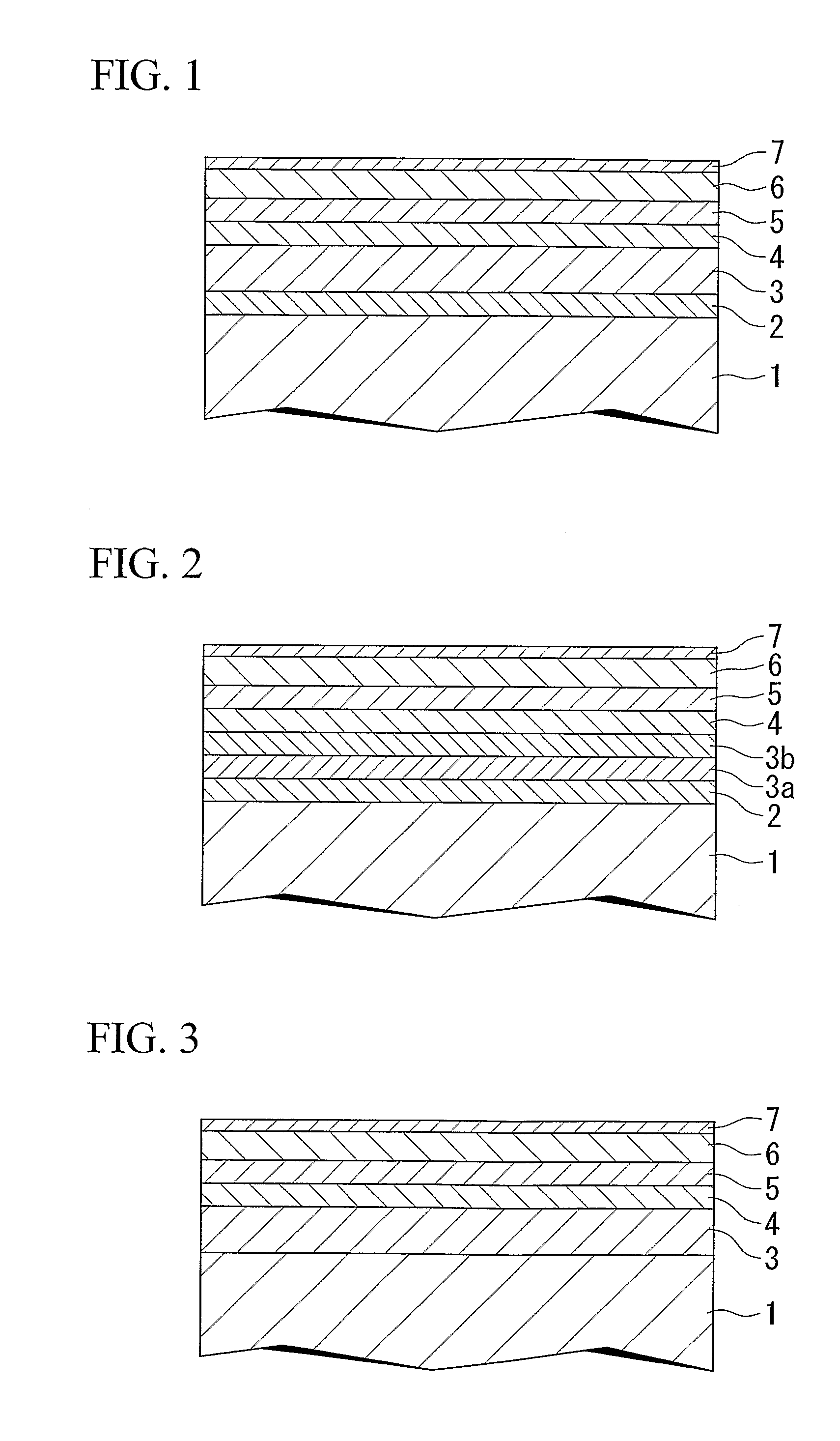
[0194] The magnetic recording medium shown in FIG. 3 was produced as mentioned below.

[0195] The magnetic recording medium G was produced in the same way as in Working Example 1, with the exception of not forming the hard magnetic layer 2, using Fe: 24 at %, Co: 16 at %, B: 4 at %, and C for the soft magnetic layer 3, and setting the thickness of the soft magnetic layer 3 to be 50 nm.

[0196] When magnetostatic characteristics were evaluated in the same way as in Working Example 1, and it turned out that the soft magnetic layer 3 had a magnetic anisotropy in a radial direction, the Bs was 19000 G, the Hc was 10 (Oe), and the Bs·Hc was 190 kG·Oe (1500 T·A / m). The measurement result is shown in Table 2.

TABLE 2HcRs−HnSNRmOWdPW50Bs · Hc(kOe)(—)(kOe)(dB)(dB)(nm)(kG · Oe)Working Example2(mediumG)4.41.002.222.244.371190Working Example1(mediumH)4.31.002.121.843.87116

[0197] As for the medium G of Working Example 2, values which are almost equivalent to those of the medium A of Working Examp...

working example 3

[0200] The magnetic recording medium H was produced by the same way as in Working Example 1, with the exception of using Fe: 27 at %, Co: 10 at %, and B for the soft magnetic layer 3.

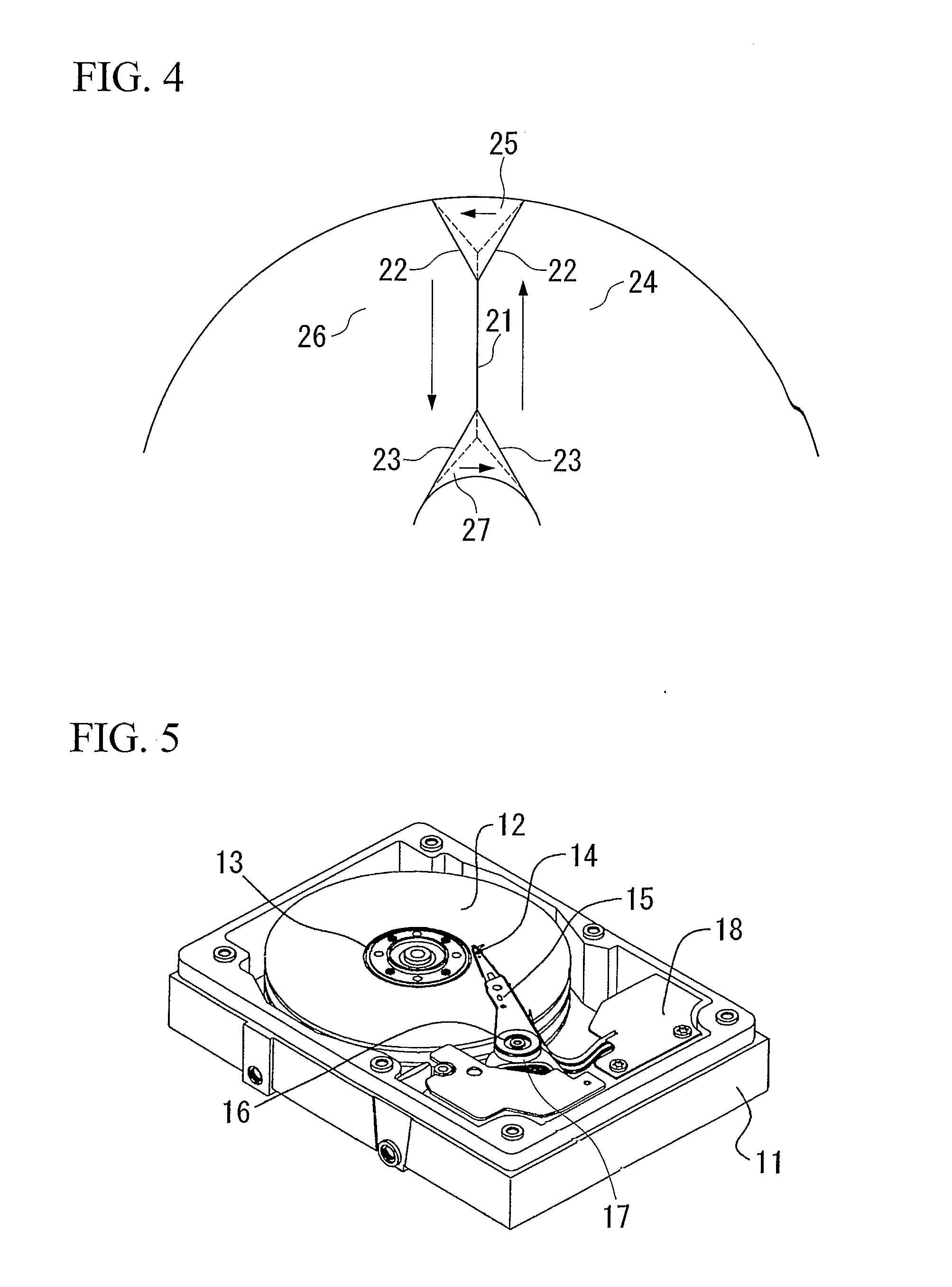
[0201] The medium H was disposed to a space between two electromagnets, and the hard magnetic layer 2 was magnetized, by generating the magnetic field of 10000 (Oe) from the electromagnet while rotating the electromagnet at 2000 rpm and moving the electromagnet in the direction of the perimeter linearly from the inner circumference, and thereafter stopping the rotation of the medium H.

[0202] The direction of the magnetostatic characteristics of the soft magnetic layer 3 and magnetic anisotropy and the direction of magnetization of the hard magnetic layer 2 were investigated similarly to Working Example 1.

[0203] The Bs of the soft magnetic layer 3 was 16000 G, the Hc was 1.0 (Oe), and the Bs·Hc was 16 kG·Oe. It turned out that although the magnetic anisotropy of the soft magnetic layer 3 was directed ...


PUM

PropertyMeasurementUnit
thicknessaaaaaaaaaa
coercive forceaaaaaaaaaa
thicknessaaaaaaaaaa

Abstract

The magnetic recording medium of the present invention has a substrate, a perpendicular magnetic recording layer, and a soft magnetic layer formed therebetween, having a thickness of less than 100 nm, the soft magnetic layer having a magnetic anisotropy in a surface direction, and product Bs·Hc, which is a production of a saturation magnetic flux density Bs and a coercive force Hc, of not less than 79 T·A / m (10 kG·Oe). By making the thickness of the soft magnetic layer into the above-mentioned range, the magnetic anisotropy in surface direction can be stabilized. magnetostatic energy can be increased sufficiently by making the Bs·Hc the above-mentioned range. Therefore, generating of the magnetic wall in the soft magnetic layer can be suppressed, the noise generating from the soft magnetic layer can be suppressed, and a high-density recording is enabled.

Description

[0001] Priority is claimed on Japanese Patent Application No. 2004-091014, filed Mar. 26, 2004, and U.S. Provisional Patent Application No. 60 / 558,556 filed Apr. 2, 2004, the contents of which are incorporated herein by reference.TECHNICAL FIELD [0002] The present invention relates to a magnetic recording medium which may be used in a hard disk drive or the like, to a manufacturing method therefor, and to a magnetic record reproducer. BACKGROUND ART [0003] Because a perpendicular magnetic recording system can reduce the magnetization transition region which is the boundary of a recorded bit by turning the magnetization easy axis of a magnetic recording layer in the perpendicular direction to a substrate, the perpendicular magnetic recording system is one which is suitable for improving recording density. [0004] As a magnetic recording medium using the perpendicular magnetic recording system, one that is called a perpendicular two-layer medium, in which a soft magnetic layer is forme...

Claims


Application Information

Patent Timeline
Patent Type & Authority Applications(United States)
IPC IPC(8): G11B5/31G11B5/66G11B5/667G11B5/73G11B5/84H01F10/06H01F10/08H01F10/16
CPCB82Y25/00G11B5/66H01F10/3222H01F10/08G11B5/667
Inventor NAKAMURA, FUTOSHITANAKA, TSUTOMUAOYAGI, YUKASHIMIZU, KENJISAKAI, HIROSHISAKAWAKI, AKIRA
Owner KK TOSHIBA
Why Eureka
Try Eureka