
Stator for birotor power generator and manufacturing process thereof

A manufacturing process and generator technology, applied in the field of the stator for a dual-rotor generator and its manufacturing process, can solve the problems of the power generation efficiency of the generator not having any effect, the limitation of the number of excitation coils 6, and the generation of heat, etc., so as to achieve weight reduction, Effect of improving power generation efficiency and eliminating iron loss

Active Publication Date: 2022-01-14
昌乐县电器设备总厂
View PDF18 Cites 0 Cited by
  • Summary
  • Abstract
  • Description
  • Claims
  • Application Information

AI Technical Summary

Problems solved by technology

[0006] The above scheme has the following defects: firstly, the support frame 10 as the skeleton does not have any effect on the power generation efficiency of the generator, and the support frame 10 occupies a certain space so that the number of excitation coils 6 wound on the iron core unit 12 is limited , the support frame 10 separates the excitation coil 6 on its left and right sides, which will generate a certain degree of iron loss and generate a certain amount of heat; in addition, there are also iron losses at the bayonet joints on both sides of the middle of the core unit 7

Method used


Image

  • Stator for birotor power generator and manufacturing process thereof
  • Stator for birotor power generator and manufacturing process thereof
  • Stator for birotor power generator and manufacturing process thereof

Examples


Embodiment Construction

[0052] The specific implementation manners of the present invention will be further described in detail below in conjunction with the accompanying drawings and embodiments. The following examples are used to illustrate the present invention, but are not intended to limit the scope of the present invention.

[0053] In the description of this application, it is to be understood that the terms "center", "upper", "lower", "front", "rear", "left", "right", "vertical", "horizontal", The orientations or positional relationships indicated by "top", "bottom", "inner", "outer", etc. are based on the orientations or positional relationships shown in the drawings, and are only for the convenience of describing the application and simplifying the description, rather than indicating or implying References to devices or elements must have a particular orientation, be constructed, and operate in a particular orientation and therefore should not be construed as limiting the application.

[0...


PUM


Abstract

The invention discloses a stator for a birotor power generator. Thestator comprises a plurality of iron core units which are annularly arranged, wherein excitation coils are wound on the iron core units, supporting plates are inserted between the intervals of the iron core units, the top ends of the supporting plates abut against the inner wall of a shell, and the excitation coils are fixedly connected with the iron core units and the supporting plates. The manufacturing process of the stator comprises the following steps of: 1, inserting and fixing iron core units in notches of a supporting frame; 2, winding excitation coils on the iron core units; 3, inserting supporting plates into the gaps of the iron core units; 4, fixedly connecting the iron core units, the excitation coils and the supporting plates; 5, taking out the supporting frame; 6, winding the residual excitation coils; and 7, fixedly connecting the excitation coils with the iron core units. According to the stator and the manufacturing process thereof, higher magnetic flux density can be generated, the power generation efficiency of a power generator is improved, and the stability of the stator structure is ensured.

Description

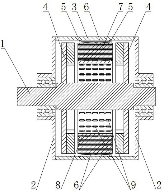
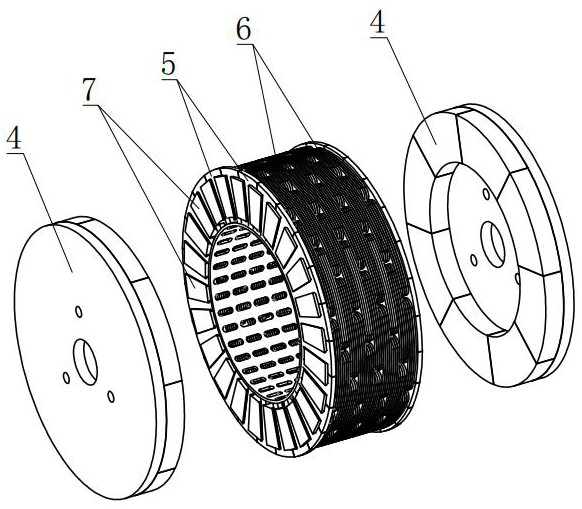
technical field [0001] The invention relates to the field of generators, in particular to a stator for a dual-rotor generator and a manufacturing process thereof. Background technique [0002] The generator is based on the law of electromagnetic induction and the law of electromagnetic force. The general principle of its construction is to use appropriate magnetic and conductive materials to form a magnetic circuit and circuit for mutual electromagnetic induction to generate electromagnetic power and achieve the purpose of energy conversion. Due to the inevitable existence of various forms of energy loss in the process of energy conversion, resulting in the reduction of energy conversion efficiency, how to minimize energy loss to improve energy conversion efficiency is an important issue that technicians in the field of generators continue to explore. . [0003] A conventional generator generally includes a housing 3, a stator, a rotor 4, a rotor shaft 1, and an excitation ...

Claims


Application Information

Patent Timeline
Patent Type & Authority Applications(China)
IPC IPC(8): H02K16/02H02K1/20H02K1/18H02K15/02H02K15/06
CPCH02K16/02H02K1/20H02K1/182H02K1/2793H02K15/02H02K15/06Y02E10/72
Inventor 肖振霞肖光娟李佳怡
Owner 昌乐县电器设备总厂
Learn More