Dual function splice component for mechanical splice connector

a technology of mechanical splice connector and component, which is applied in the field of fiber optic connector, can solve the problems of requiring additional materials, affecting the field optical fiber, and unable to reverse and rework the splice, so as to eliminate the effect of positioning

Active Publication Date: 2007-09-20
CORNING OPTICAL COMM LLC
View PDF17 Cites 8 Cited by
  • Summary
  • Abstract
  • Description
  • Claims
  • Application Information

AI Technical Summary

Benefits of technology

[0007] In one aspect, the present invention is directed to a fiber optic mechanical splice connector having a dual function connector element operable for providing both optical fiber alignment and field fiber strain relief. While traditional fiber optic connectors utilize one element of the connector to align the optical fibers for splicing and a separate element of the connector for strain relieving the buffered portion of the field optical fiber, a single element of the present invention performs both functions. The use of a single element of the connector for both functions eliminates positioning effects caused by the two separate elements moving independently of each other during environmental changes, as well as in normal operation.
[0010] In yet another aspect, the first groove and the second groove are each preferably positioned on the surface of the splice component opposite a projection, such as a rib, keel or the like. The use of separate projections is also possible, as well as the use of separate projections having different geometries and sizes corresponding to the different sized grooves to compensate for the different forces required for the mechanical splicing of bare optical fibers and the retention of the field optical fiber. Prior to insertion into the connector, the end of the field optical fiber is stripped and cleaved to a specified length. This leaves a section of bare glass fiber protruding from the coated portion, or the coated and buffered portion, of the field optical fiber. The field optical fiber is inserted into the open rear end of the connector opposite the ferrule and is guided between the splice components. The bare glass portion of the field optical fiber enters the splice components through the larger retention grooves. The bare glass portion of the field optical fiber continues through the retention grooves and the transition zone into the smaller alignment groove. Once in the alignment groove, the bare glass portion of the field optical fiber is advanced until it comes into physical contact with the end of the stub optical fiber that is disposed within and extends rearwardly from the ferrule. When the ends of the two fibers make contact, a sufficient length of the coated or buffered portion of the field optical fiber is disposed within the retention grooves. The connector further includes a cam member movable between an initial, un-actuated position allowing the splice components to remain apart to facilitate insertion of the field optical fiber, and a final, actuated position in which the cam member biases the splice components towards one another to align the stub optical fiber and the field optical fiber therebetween. In a particular embodiment, the cam member is rotated while the end of the field optical fiber is in physical contact with the end of the stub optical fiber. Rotation of the cam member causes an interior cam surface, having a predetermined geometry, to come into contact with the projections on the splice components, and thereby bias the splice components around the bare glass portions of the optical fibers and the coated or buffered portion of the field optical fiber, thus providing both alignment and strain relief. Upon cam actuation, the alignment region and the retention region are constrained within the same element of the connector, and specifically the splice components, which eliminates positioning problems that occur when separate elements of the connector are utilized for the mechanical splicing and strain relief functions. The field optical fiber may be removed from the connector after it has been initially terminated to the connector by returning the cam to the initial, un-actuated position, thereby releasing the clamping forces on both the bare glass portion and the coated or buffered portion of the field optical fiber.

Problems solved by technology

A drawback to the conventional strain relief technique for mechanical splice connectors is that once the field optical fiber is strain relieved, the splice cannot be reversed and reworked without destroying the connector assembly and potentially damaging the field optical fiber.
A significant drawback to these other mechanical splice connectors is that optical fiber alignment and strain relief must be performed in more than one step and using more than one element of the connector, thus requiring additional materials, as well as additional time and labor cost to install the connector.
A further drawback to these conventional mechanical splice connectors is that once the optical fibers are strain relieved by applying a crimp, the splice cannot be reversed without destroying the connector assembly or potentially damaging the field optical fiber.

Method used


Image

  • Dual function splice component for mechanical splice connector
  • Dual function splice component for mechanical splice connector
  • Dual function splice component for mechanical splice connector

Examples


Embodiment Construction

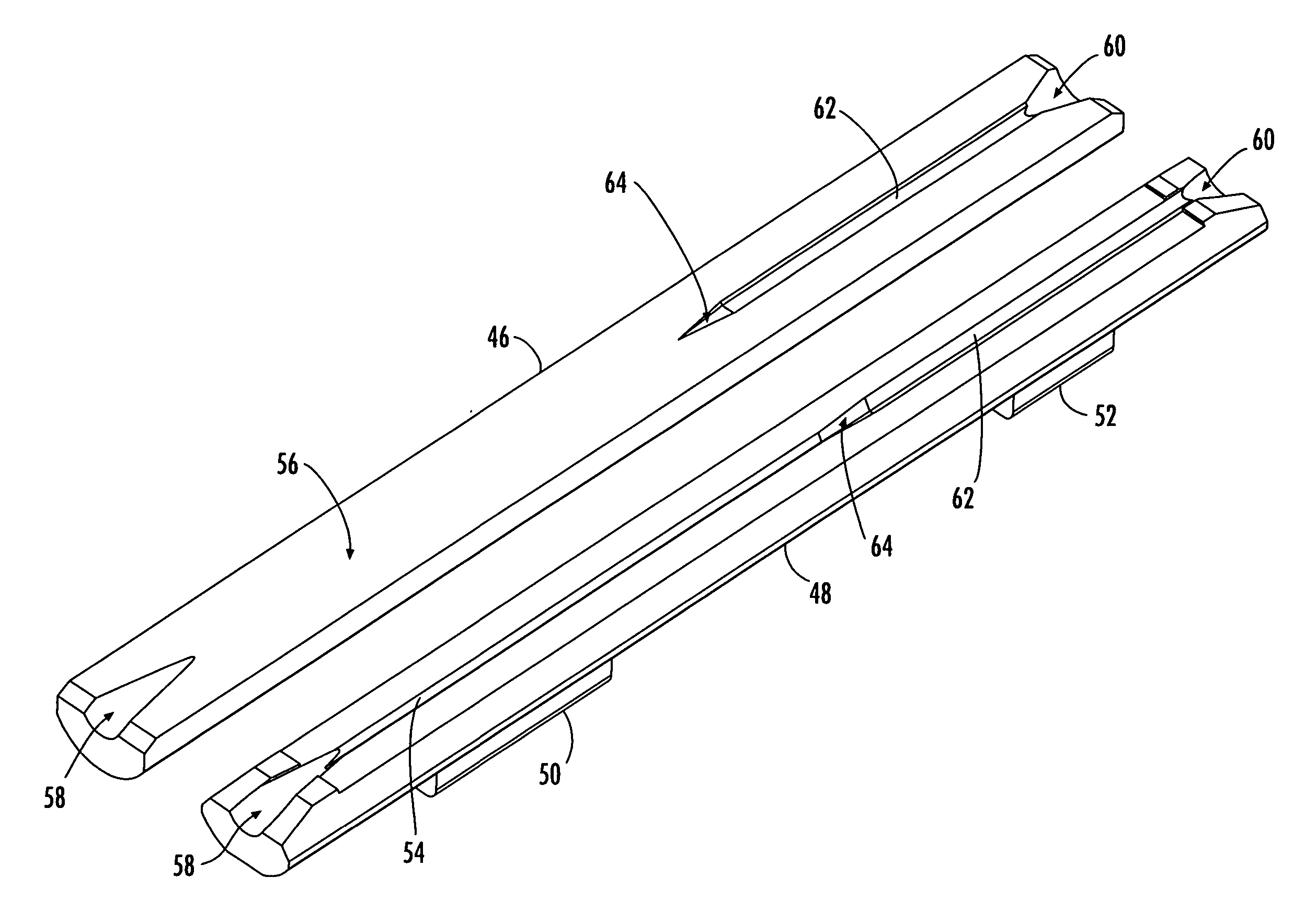
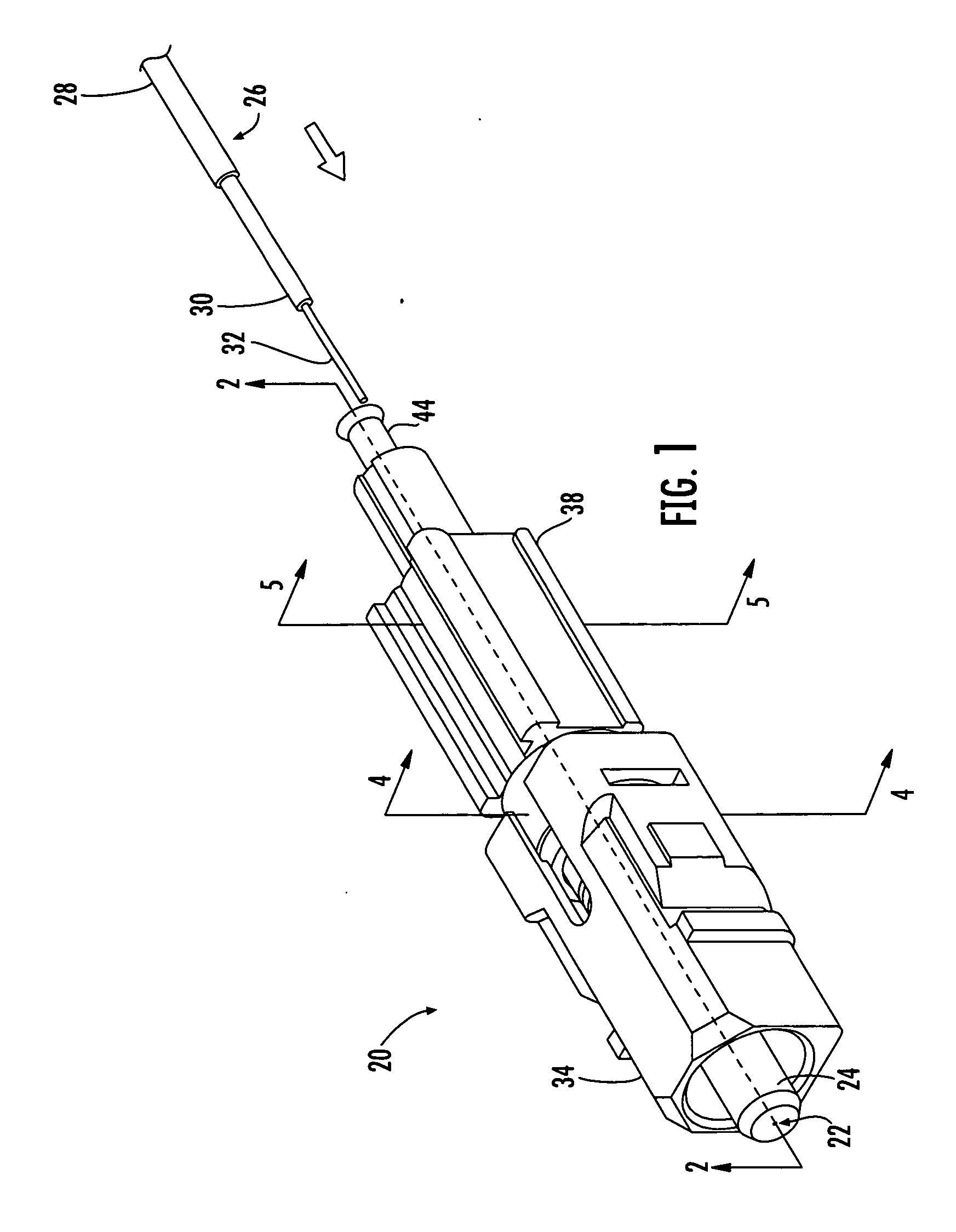
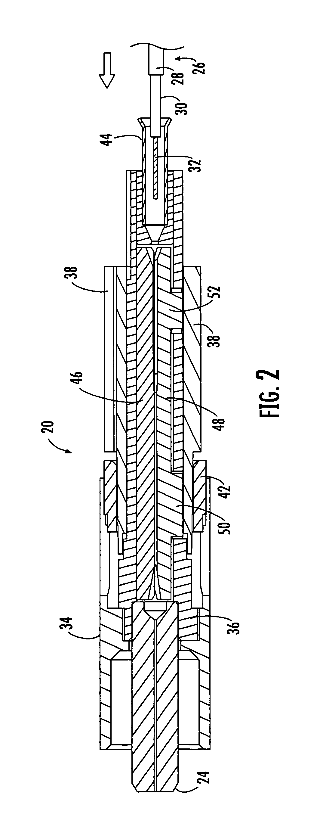
[0018] Reference will now be made in detail to presently preferred embodiments of the invention, examples of which are illustrated in the accompanying drawings. Whenever possible, the same reference numerals are used throughout the drawings to refer to the same or like parts. Although a dual function connector element operable for providing both optical fiber alignment and strain relief is shown in the accompanying drawings as one or more splice components of a particular fiber optic mechanical splice connector, it is envisioned that the dual function connector element may be any component used in any now known or hereafter devised mechanical splice connector that facilitates the splicing of two or more optical fibers, as well as the retention of one or both of the optical fibers. The broad concepts of the present invention may also be applied to any optical connection between mating optical fibers, such as a mechanical or fusion splice connection utilizing a splice component or spl...


PUM

PropertyMeasurementUnit
outer diameteraaaaaaaaaa
diameteraaaaaaaaaa
diameteraaaaaaaaaa

Abstract

A fiber optic mechanical splice connector including a single connector element operable for providing optical fiber alignment and strain relief includes opposed splice components that define first and second grooves for receiving the bare glass portions of mating optical fibers, as well as the coated or buffered portion of at least one of the optical fibers when the splice components are biased together by an actuator. The mating optical fibers are aligned while the coated or buffered portion of one of the optical fibers is retained within the same connector element, thus eliminating positioning problems that occur when separate connector elements are utilized for fiber alignment and strain relief. The splice components may be unbiased to allow removal of at least one of the mating optical fibers without destroying the connector assembly or potentially damaging the optical fibers.

Description

BACKGROUND OF THE INVENTION [0001] 1. Field of the Invention [0002] The present invention relates generally to a fiber optic connector having a single connector element for providing both optical fiber alignment and strain relief, and more specifically, to a mechanical splice connector including a splice component operable for aligning and retaining the stub optical fiber and the adjoining field optical fiber, as well as strain relieving the field optical fiber. [0003] 2. Technical Background [0004] A key objective contributing to the proper function of a fiber optic mechanical splice connector is the alignment of the mating optical fibers within the connector. Alignment is typically accomplished by applying a biasing force to a splice component to accurately align the stub optical fiber of the connector with the mating field optical fiber. Conventional mechanical splice connectors typically include a pair of opposed splice components, wherein at least one of the splice components d...

Claims


Application Information

Patent Timeline
Patent Type & Authority Applications(United States)
IPC IPC(8): G02B6/255
CPCG02B6/255G02B6/3806G02B6/3846G02B6/38875
Inventor DOSS, DONALDLEYVA, DANIELBARNES, BRANDON
Owner CORNING OPTICAL COMM LLC
Why Eureka
Try Eureka