Wireless communication system, wireless communication method, and signal processing program therefor

a wireless communication and wireless communication technology, applied in the direction of power management, receiving, monitoring of receipts, etc., can solve the problem that the power consumption of the transmitter for digital signal processing cannot be reduced, and achieve the effect of increasing the number of bits, reducing the power consumption of the transmitter, and speeding up the operation

Inactive Publication Date: 2007-09-20
NEC CORP
View PDF5 Cites 14 Cited by
  • Summary
  • Abstract
  • Description
  • Claims
  • Application Information

AI Technical Summary

Benefits of technology

[0033]Therefore, according to the signal processing program for wireless communication, the wireless communication systems on the transmission side and on the reception side can perform almost identical level of signal processes individually and rapidly, and the number of bits can be processed to be increased or reduced at a prescribed digital signal processing. Accordingly, when the signal processing program is executed for a wireless communication system, an operation can be performed rapidly and power consumption of a transmitter can be lowered effectively in this wireless communication system.
[0034]As described above, according to the present invention, bit widths for signal processes at the digital signal processing are varied in response to a condition of the transmission path of the line, so that a wireless communication system, a wireless communication apparatus, a wireless communication method, and a signal processing program therefor can be provided which are capable of lowering the power consumption for the digital signal processing in response to a condition of a transmission path, especially on the transmission side.

Problems solved by technology

However, according to the conventional technique in Patent Document 1, the power consumption of the receiver can be reduced, by varying a bit width for digital signal processing of the receiver in response to an error rate (that is, an error rate of a transmission path condition), but the power consumption of the transmitter for the digital signal processing cannot be reduced.

Method used


Image

  • Wireless communication system, wireless communication method, and signal processing program therefor
  • Wireless communication system, wireless communication method, and signal processing program therefor
  • Wireless communication system, wireless communication method, and signal processing program therefor

Examples


first embodiment

[0055]Next, a first embodiment of the present invention will be explained with reference to FIGS. 1 to 5.

[0056]First of all, a substantial part of the embodiment will be presented, and then an whole structure will be described.

(Configuration)

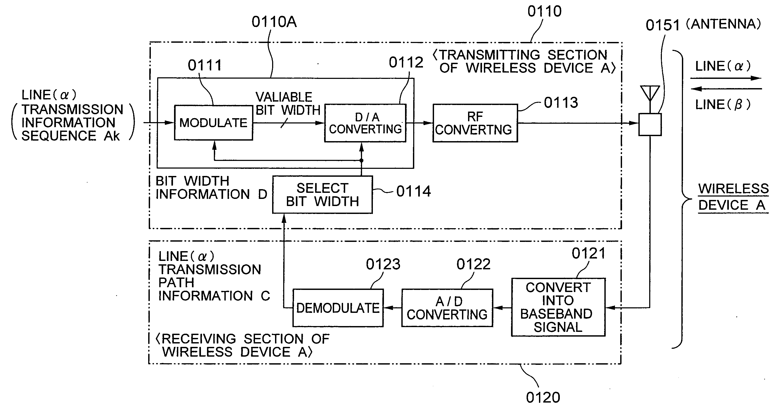
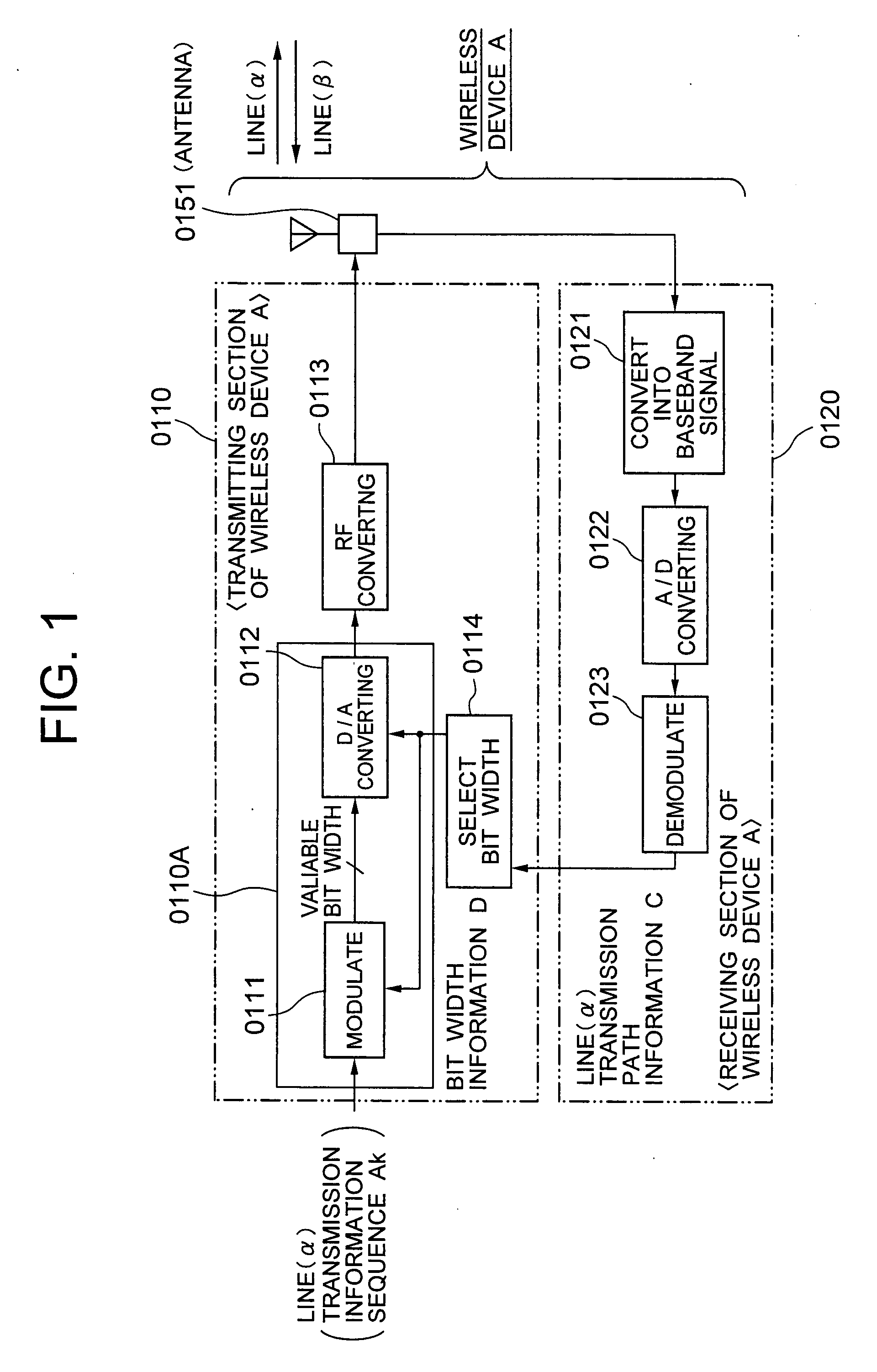
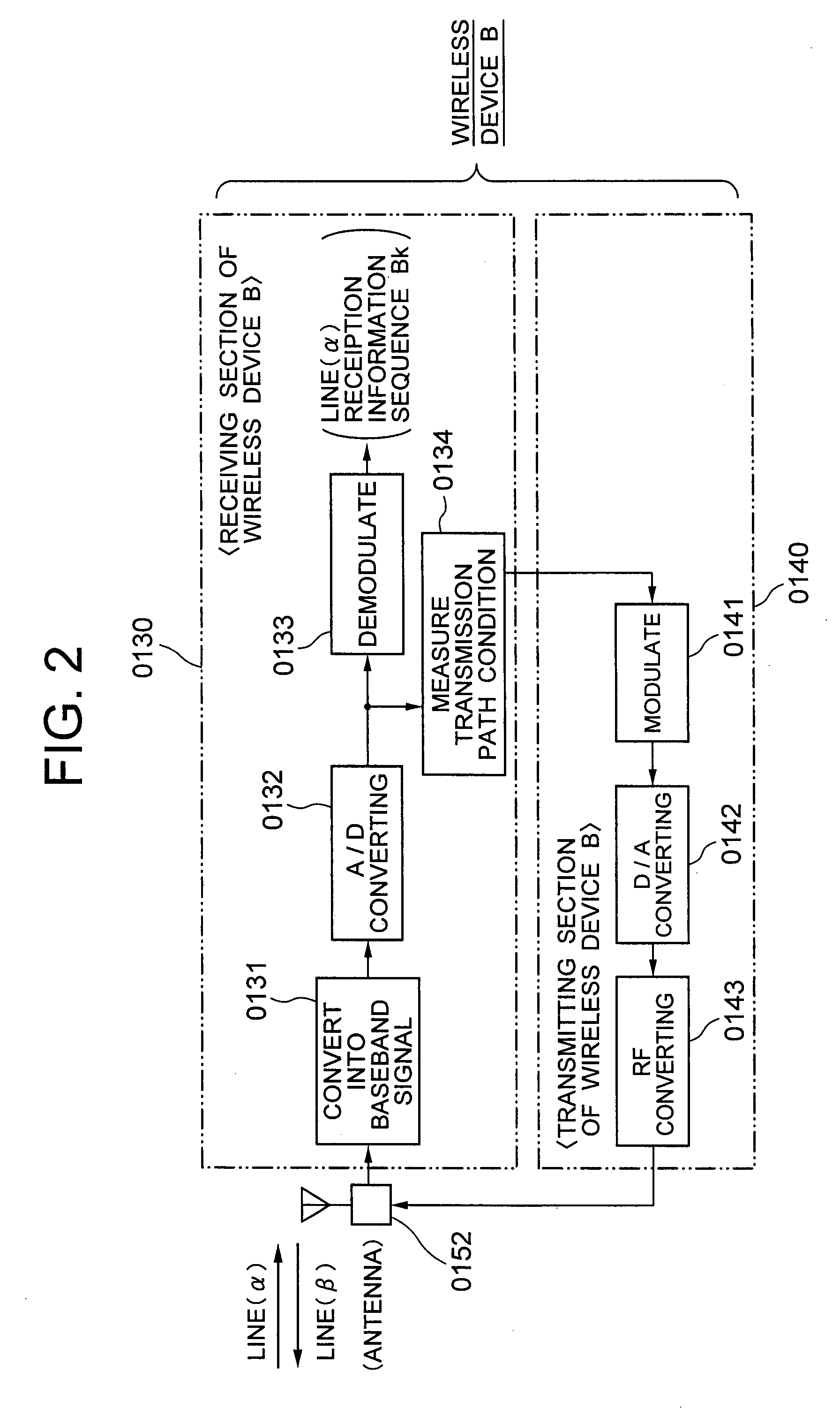
[0057]As shown in FIGS. 1 and 2, a line (α) and a line (β) are for transmission and reception in the present embodiment. A wireless device A on a transmission side as a wireless communication apparatus shown in FIG. 1 comprises a transmitting section 0110, a receiving section 0120, and an antenna unit 0151. A wireless device B on the reception side shown in FIG. 2 comprises a receiving section 0130, a transmitting section 0140, and an antenna unit 0152 of the wireless device B.

[0058]The transmitting section 0110 on the transmission side (the wireless device A) includes a digital signal processing unit 0110A, and has a function of performing communication by digital transmission or analog transmission of a signal processed by the digital signal p...

second embodiment

[0104]Next, a second embodiment according to the present invention will be explained with reference to FIGS. 6 to 8.

[0105]Here, the same numerals are used for the same components as in the first embodiment mentioned above.

[0106]FIG. 6 is a block diagram showing the second embodiment illustrating the wireless device A on the transmission side. For the wireless device B on the reception side, the same drawing as in FIG. 2, mentioned above, is used.

[0107]The second embodiment, as shown in FIG. 6, is an example applied the adaptive modulation / demodulation control in which a modulation / demodulation mode for the line (α) is varied in response to a transmission path condition after transmission / reception through the lines (α) and (β).

[0108]In FIG. 6, a transmission side (the wireless device A) comprises a transmitting section 0510 of the wireless device A, a receiving section 0520 of the wireless device A, and an antenna unit 0551.

[0109]The transmitting section 0510 of the wireless device ...

embodiment (

2)

[0175]Next, an embodiment (2) will be explained as another specific example with reference to FIGS. 15 to 18.

[0176]In the embodiment (2), an example will be described where transmission and reception are performed through lines (α) and (β), and the line (α) employs an adaptive modulation / demodulation control which is corresponding to QPSK, 16 QAM, 64 QAM, and 256 QAM, as a modulation / demodulation mode, and further employs a spreading unit.

[0177]As shown in FIG. 15, a transmission side in the embodiment (2) comprises a transmitting section 1410 of a wireless device A for performing a transmitting processing for the line (α), a receiving section 1420 of the wireless device A for performing a receiving processing for the line (β), and an antenna unit 1431.

[0178]Further, as shown in FIG. 16, a reception side in the embodiment (2) comprises a receiving section 1510 of a wireless device B for performing a receiving processing for the line (α), a transmitting section 1520 of the wireless...


PUM


Abstract

To achieve a wireless communication apparatus capable of lowering power consumption for a digital signal processing of a transmitter in response to a transmission path condition.
A wireless communication system performs communication by digital transmission or analog transmission of a signal processed by a digital signal processing unit in a transmitting section on a transmission side toward a reception side through a line, wherein a transmission path condition of the line is measured on the reception side, the transmission path condition is transmitted to the transmission side using a reverse line with respect to the above described line, and a bit width for signal processing of digital signal processing units such as a modulating unit and a digital/analog converting unit is varied by a bit width selecting unit in response to the transmission path condition of the line notified by the reverse line on the transmission side.

Description

BACKGROUND OF THE INVENTION[0001]1. Field of the Invention[0002]The present invention relates to a wireless communication system, a wireless communication apparatus, a wireless communication method, and a signal processing program therefor in performing wireless communication by an analog transmission system and a digital transmission system, wherein, in particular, signal bit width is varied according to a condition of a transmission path on a digital signal processing at a transmitting section.[0003]2. Description of the Related Art[0004]Wireless transmission systems using light or electromagnetic waves for carrier waves are classified broadly into an analog transmission system and a digital transmission system. The wireless transmission is achieved by a wireless transceiver in which a modulation / demodulation processing is performed by a computer having an analog circuit or a digital circuit, and a control program.[0005]FIG. 19 shows an example of a receiver in a conventional wire...

Claims


Application Information

Patent Timeline
Patent Type & Authority Applications(United States)
IPC IPC(8): H04Q7/20H04M11/00H04W52/04
CPCH04L1/0003H04L1/0033H04B17/24Y02B60/50H04W52/04
Inventor FUTATSUGI, YASUNORITANAKA, TOMOZOU
Owner NEC CORP
Why Eureka
Try Eureka