Cryogenic aerogel insulation system

a technology of cryogenic aerogel and insulation system, which is applied in the direction of positive displacement liquid engine, container discharge method, separation process, etc., can solve the problems of high manufacturing cost of vacuum insulation equipment, high cost of hard vacuum, and notoriously difficult maintenance of hard vacuum over the useful life, etc., and achieve high specific area

Active Publication Date: 2007-09-27
PRAXAIR TECH INC
View PDF16 Cites 30 Cited by
  • Summary
  • Abstract
  • Description
  • Claims
  • Application Information

AI Technical Summary

Benefits of technology

[0006] (C) cooling at least one wall of the aerogel containing insulation space to a temperature less than 190 K.
[0007] As used herein the term “condensable gas” means a gas having a vapor pressure at the cold condition which is significantly lower than the pressure which would be expected by applying the ideal

Problems solved by technology

The hard vacuum required is expensive to produce, requiring long pump out times at elevated temperature.
This results in a high manufacturing cost for vacuum insulated equipment.
Once obtained, the hard vacuum is notoriously difficult to maintain over the useful life of the equipment, which may typically be from 15 to 20 years, and it is fou

Method used


Image

  • Cryogenic aerogel insulation system
  • Cryogenic aerogel insulation system

Examples


Embodiment Construction

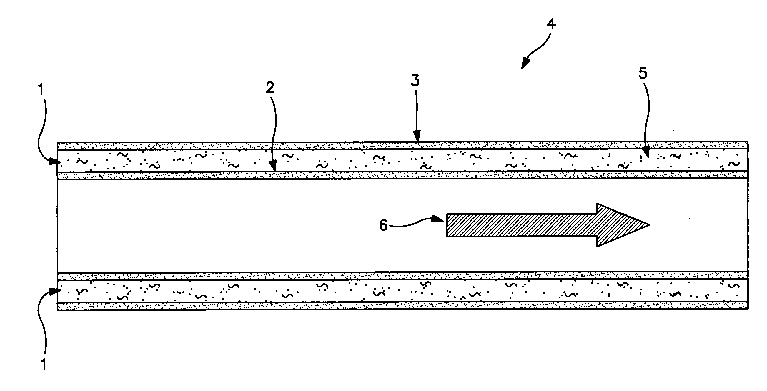
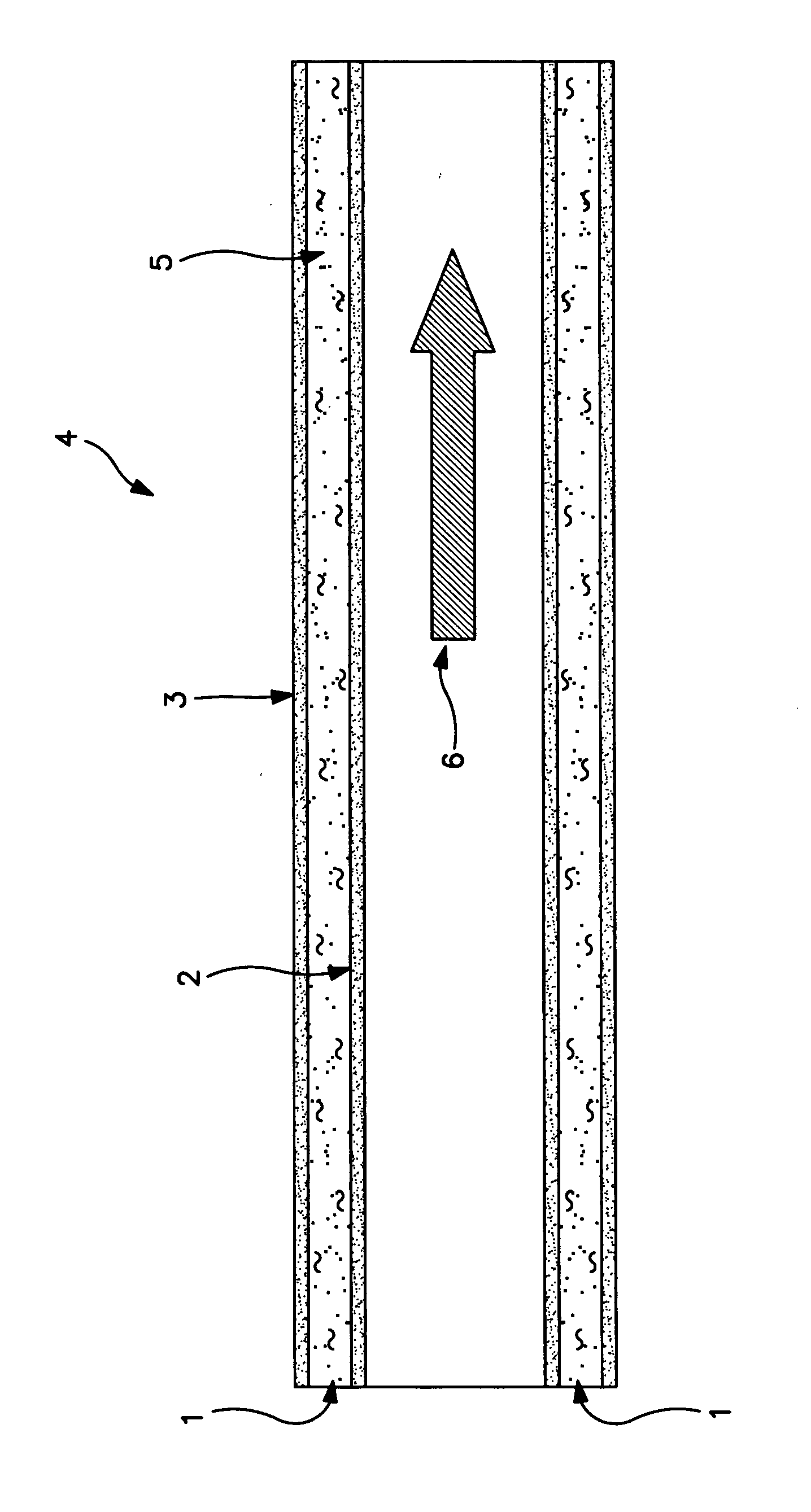
[0009] The invention is applicable for use with any double walled structure or vessel such as a double-walled pipe or a double walled tank. The FIGURE illustrates a section of double-walled pipe or conduit and the invention will be discussed in greater detail with reference to the FIGURE.

[0010] Referring now to the FIGURE, insulation space 1 is the volume defined by inner wall 2 and outer wall 3 of double walled conduit 4. Insulation space 1 contains aerogel 5 which may be in the form of an aerogel composite such as a blanket which comprises aerogel combined with fibrous batting such as polyester, fiberglass, carbon fiber, silica fiber and mixtures thereof. Preferably at least 75 percent of the volume of the insulation space is filled with aerogel or aerogel composite.

[0011] Any suitable aerogel may be used in the practice of this invention. The preferred aerogel in the practice of this invention is silica aerogel. Aerogel can be produced as a monolithic block, as a particulate in...


PUM

PropertyMeasurementUnit
Temperatureaaaaaaaaaa
Lengthaaaaaaaaaa
Lengthaaaaaaaaaa

Abstract

A method for establishing a cryogenic insulation system wherein aerogel is provided to a sealable insulation space which is pressurized and depressurized, preferably using carbon dioxide gas, and cooled to cryogenic temperatures typically by the application of refrigeration from cryogenic liquid.

Description

TECHNICAL FIELD [0001] This invention relates generally to insulation systems and, more particularly, to insulation systems intended for use at cryogenic temperatures. BACKGROUND ART [0002] Conventional cryogenic vacuum insulation systems for double walled vessels require a hard vacuum, typically less than 1 micron Hg at 0° C. The purpose of the vacuum is to reduce gas conduction / convection. The hard vacuum required is expensive to produce, requiring long pump out times at elevated temperature. This results in a high manufacturing cost for vacuum insulated equipment. Once obtained, the hard vacuum is notoriously difficult to maintain over the useful life of the equipment, which may typically be from 15 to 20 years, and it is found in practice that, despite all the precautions, the pressure in the vacuum space inevitably rises causing a dramatic loss of performance. One alternative is to use foam insulation. However this insulation has much higher heat leak than vacuum insulation. Un...

Claims


Application Information

Patent Timeline
IPC IPC(8): F17C13/00B01D8/00
CPCF16L59/065F17C2203/0325F16L59/141F17C3/02F17C3/04
Inventor JIBB, RICHARD JOHNROYAL, JOHN HENRIWHITE, NORMAN HENRYSCHWEICHLER, STEVE ALLANHOBBS, WEVONE
Owner PRAXAIR TECH INC
Why Eureka
Try Eureka