Air conditioning unit, operatable with carbon dioxide, for vehicles and method for operating the air conditioning unit

a technology of air conditioning unit and carbon dioxide, which is applied in the direction of refrigeration components, transportation and packaging, light and heating equipment, etc., can solve the problems of assembly and operation complications, the mechanical integration of the main compressor is relatively expensive, and the process performance decreases relatively distinctly, so as to reduce the optimal high pressure and reduce the mass flow a little

Active Publication Date: 2007-09-27
HANON SYST
View PDF6 Cites 26 Cited by
  • Summary
  • Abstract
  • Description
  • Claims
  • Application Information

AI Technical Summary

Benefits of technology

[0038]Because of the expansion at the external heat exchanger, the expanded cold refrigerant has to be transported to the evaporator with the heat input as small as possible. That is achieved by that a double pipe (coaxial pipe) is used which includes two refrigerant flows at low pressure, whereby the expanded refrigerant from the external heat exchanger preferably flows in the interior while the refrigerant coming from the evaporator is enveloped. The coaxial pipe is not primarily intended to transfer heat between both refrigerant flows, but to keep the heat input from the outside as small as possible.
[0047]The air conditioning unit can be provided with an inner heat exchanger (IHX in the following) which is, on the one hand, integrated into the line train between the main compressor and the internal heat exchanger and, on the other hand, into the line train between the second external heat exchanger and the expansion machine. Hereby, an efficiency of 5 to 50% of the IHX is aimed at, distinctly below current CO2-units. In this case the internal heat exchanger, compared with the process B, is intended to reduce the mass flow a little. In the process B, the IHX is intended to provide the required refrigeration capacity at high ambient temperatures and significantly reduce the optimal high pressure at the maximum coefficient of performance.

Problems solved by technology

A problem is that at high ambient temperatures the coefficient of performance of the process decreases relatively distinctly compared with current refrigerants, or the alternatives thereof.
The mechanical integration into the main compressor is relatively expensive and the efficiency chain is critical for the conversion into electrical power.
A problem is that the use of the described expansion-compression machine in mobile applications such as automobiles implies assembly and operation complications due to the design and the dimensions resulting therefrom, as the automobile industry aims at the miniaturization of the automobile components.

Method used


Image

  • Air conditioning unit, operatable with carbon dioxide, for vehicles and method for operating the air conditioning unit
  • Air conditioning unit, operatable with carbon dioxide, for vehicles and method for operating the air conditioning unit
  • Air conditioning unit, operatable with carbon dioxide, for vehicles and method for operating the air conditioning unit

Examples


Embodiment Construction

[0085]The following description is merely exemplary in nature and is not intended to limit the present disclosure, application, or uses. It should also be understood that throughout the drawings, corresponding reference numerals indicate like or corresponding parts and features. In respect of the methods disclosed, the steps presented are exemplary in nature, and thus, are not necessary or critical.

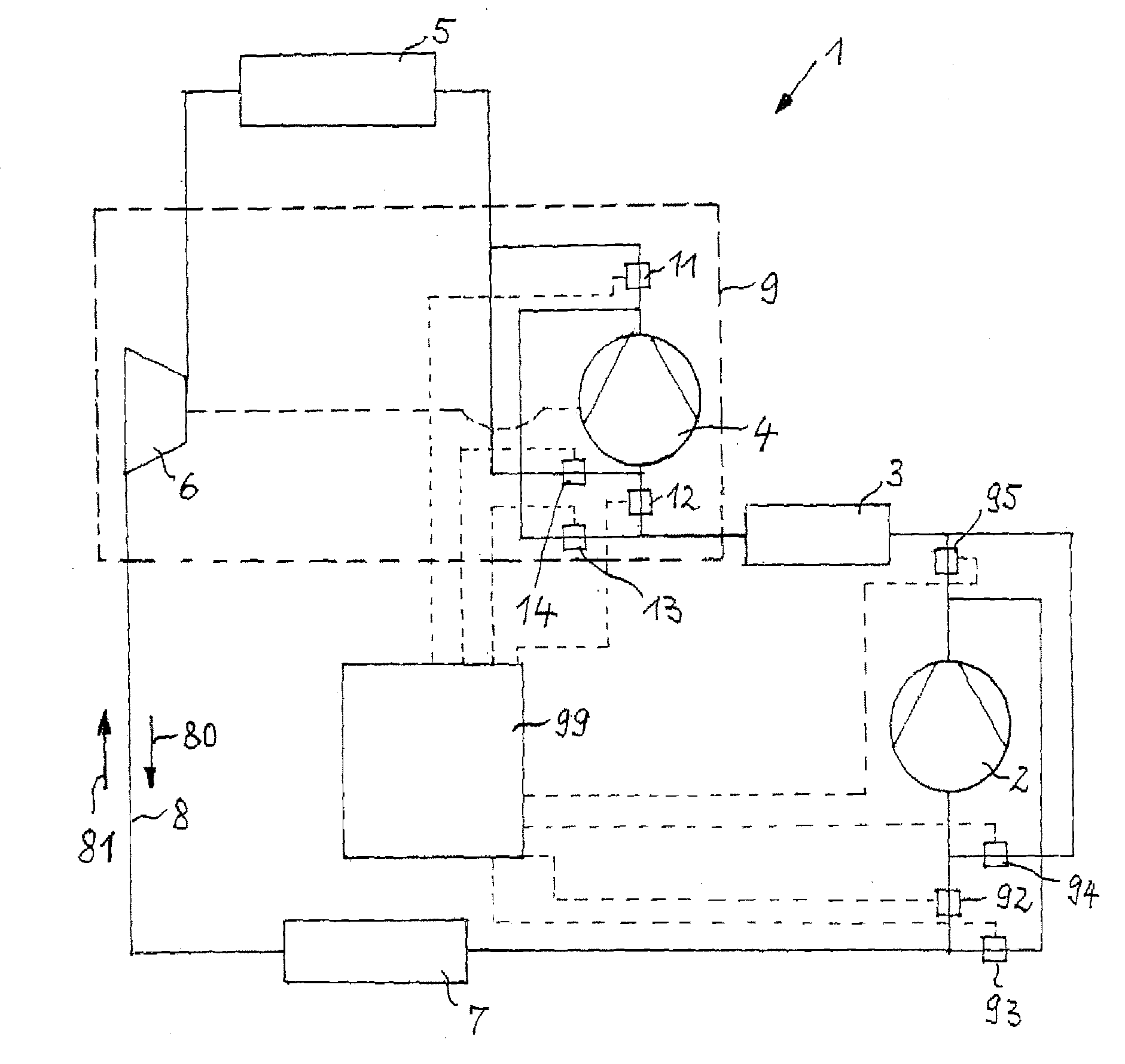
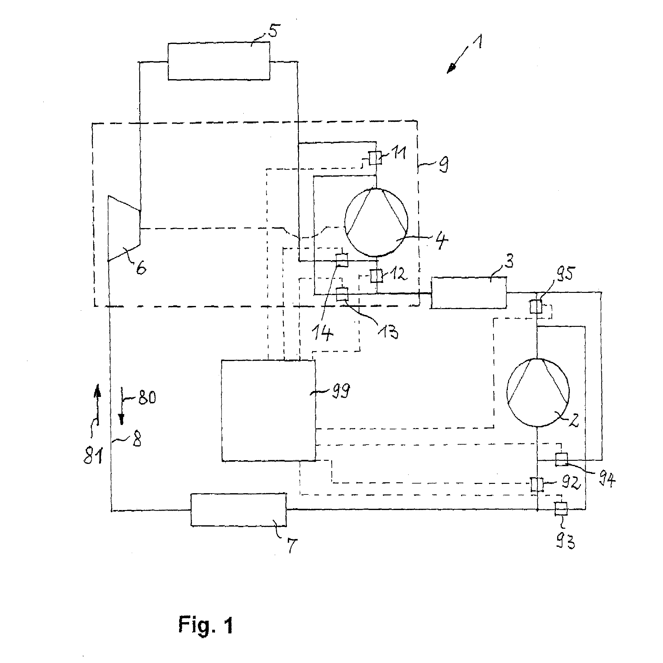
[0086]In the following, the FIGS. 1,3,4 are considered largely in common, whereby in FIG. 1 the air conditioning unit 1 according to the invention is shown and in FIGS. 3,4 the use of toothed gear machines is provided.

[0087]The air conditioning units 1,10 operatable with carbon dioxide, with work-doing expansion of the carbon dioxide, the energy of which serves to compress the carbon dioxide in a second compression stage, include at least a main compressor 2 to compress from low pressure to medium pressure in form of a first compression stage, a first external heat exchanger 3, a subsidia...


PUM


Abstract

An air conditioning unit for vehicles with work-doing expansion of the carbon dioxide is provided, the air conditioning unit including a combined refrigeration and heat pump circuit, wherein the air conditioning unit is switchably configured to change a flow direction of a refrigerant for switchable operation from the refrigeration circuit to the heat pump circuit. A method for operating the air conditioning unit is also provided.

Description

CROSS-REFERENCE TO RELATED APPLICATIONS[0001]This application claims priority to German Provisional Patent Application No. 10 2006 014 430.9, filed Mar. 27, 2006, and German Non-Provisional Patent Application No. 10 2007 006 993.8, filed Feb. 7, 2007, the entire disclosures of which are incorporated herein by reference.FIELD OF THE INVENTION[0002]The invention relates to an air conditioning unit, operatable with carbon dioxide, for vehicles and a method for operating the air conditioning unit with the carbon dioxide doing work during expansion.BACKGROUND OF THE INVENTION[0003]A transcritical process traditionally used in automobile air conditioning applications (solid lines, process B) is given in a pressure / enthalpy diagram shown in FIG. 2, whereby the process is described by a compression (state 1″-state 2″), a heat output to an external heat ex-changer (state 2″-state 3″), the high-pressure side of an internal heat exchanger (state 3″-state 4″), an irreversible isenthalpic expans...

Claims


Application Information

Patent Timeline
Patent Type & Authority Applications(United States)
IPC IPC(8): F25B13/00F25B1/10
CPCB60H1/00907F25B1/10F25B9/008F25B9/06F25B13/00F25B2400/14F25B2309/06F25B2309/061F25B2313/0271F25B2313/02791F25B2400/0401F25B40/00
Inventor HEYL, PETER
Owner HANON SYST
Why Eureka
Try Eureka