Ultrasonic Flowmeter and Ultrasonic Flow Rate Measurement Method

Active Publication Date: 2007-09-27
FUJI ELECTRIC CO LTD
View PDF9 Cites 38 Cited by
  • Summary
  • Abstract
  • Description
  • Claims
  • Application Information

AI Technical Summary

Benefits of technology

[0027] A purpose of the present invention is to provide an ultrasonic flowmeter and ultrasonic flow rate measurement method which are capable of improving measurement accuracy and a measurable range without being influenced by the state of a fluid such as a flow velocity and an amount of bubbles.
[0028] Another purpose of the present invention is to accomplish a reduction of production cost and simplification of installing a detector for an ultrasonic flowmeter.
[0029] Yet another purpose of the present invention is to accomplish an improvement of measurement accuracy of a flow rate by eliminating a technical problem inherent to the pulse Doppler method in the case of a single detector while suppressing a cost increase.

Problems solved by technology

However, the method is faced with a technical problem of incapability of measuring a fluid with a small amount of impurities and of a limitation of a measurable velocity range.
Meanwhile, in order to measure a flow velocity profile over the entire area of a pipe along the measurement line, because it is not possible to carry out a subsequent measurement until the return of echo waves from the pipe wall on the other side of the pipe, it is necessary that:
Another problem with regard to the pulse Doppler method is the fact that it is not possible to detect the flow velocity close to the pipe wall on the detector side.
Both these methods, however, assume the flow of a fluid to be a convex and symmetrical flow and result in degraded flow rate measurement accuracy for asymmetrical flows such as a flow at a bend or at a merge.
Also assumed is that the flow only has an axial component, thus degraded flow rate measurement accuracy results if a radial component occurs in a flow at a bend or at a merge.
As described so far, there are advantages and disadvantages to both the pulse Doppler method and the transit time method, since the conventional method for measuring a flow rate using a single measurement instrument utilized either the pulse Doppler method or the transit time method, is faced with the technical problem of a reduced measurement accuracy or inability of measurement depending on the velocity of a fluid as the subject of measurement or the conditions such as inclusion of bubbles.

Method used


Image

  • Ultrasonic Flowmeter and Ultrasonic Flow Rate Measurement Method
  • Ultrasonic Flowmeter and Ultrasonic Flow Rate Measurement Method
  • Ultrasonic Flowmeter and Ultrasonic Flow Rate Measurement Method

Examples


first embodiment

[0072]FIG. 3 is a conceptual diagram exemplifying a comprisal of an ultrasonic flowmeter for carrying out an ultrasonic flow rate measurement method according to an embodiment of the present invention.

[0073] The ultrasonic flowmeter according to the present embodiment, being mounted onto a pipe 50 in which a fluid 51 as the subject of measurement flows, comprises a plurality of detectors 41, 42 and 43 (i.e., the transducer units) comprising a piezoelectric element, et cetera, each of which functions as an ultrasonic transmitter & receiver. That is, each of the detectors 41, 42 and 43 comprises a piezoelectric element 40a for carrying out an interconversion between an acoustic signal, such as an ultrasonic oscillation, and electric signal and a wedge body 40b, lying between the wedge body 40b and the outer wall surface of the pipe 50, for transmitting an ultrasonic oscillation generated by the piezoelectric element 40a into the pipe 50 at a predetermined incidence angle to transmit ...

second embodiment

[0087]FIG. 4 is a conceptual diagram exemplifying a comprisal of an ultrasonic flowmeter according to another embodiment of the present invention. The comprisal shown by FIG. 4 exemplifies the case of placing a detector changeover switch 35 at the front stage of the received signal amplification control unit 21 comprised by the pulse Doppler method unit 20 and sharing both of a pair of detector 41 (i.e., a first transducer unit) and detector 42 (i.e., a second transducer unit) with the pulse Doppler method unit 20 in the comprisal shown by the above described FIG. 3.

[0088] That is, the example comprisal shown by FIG. 4 reduces the number of detectors from three to two from that of theFIG. 3 by eliminating the detector 43 dedicated to the pulse Doppler method unit 20 as a result of sharing either one or both of the pair of detectors 41 and 42 used by the transit time method unit 10 by connecting the pair thereof to the pulse Doppler method unit 20 by way of the detector changeover s...

third embodiment

[0096]FIG. 6 is a block diagram exemplifying a comprisal of an ultrasonic flowmeter according to yet another embodiment of the present invention; and FIGS. 7 and 8 are conceptual diagrams describing example operations thereof.

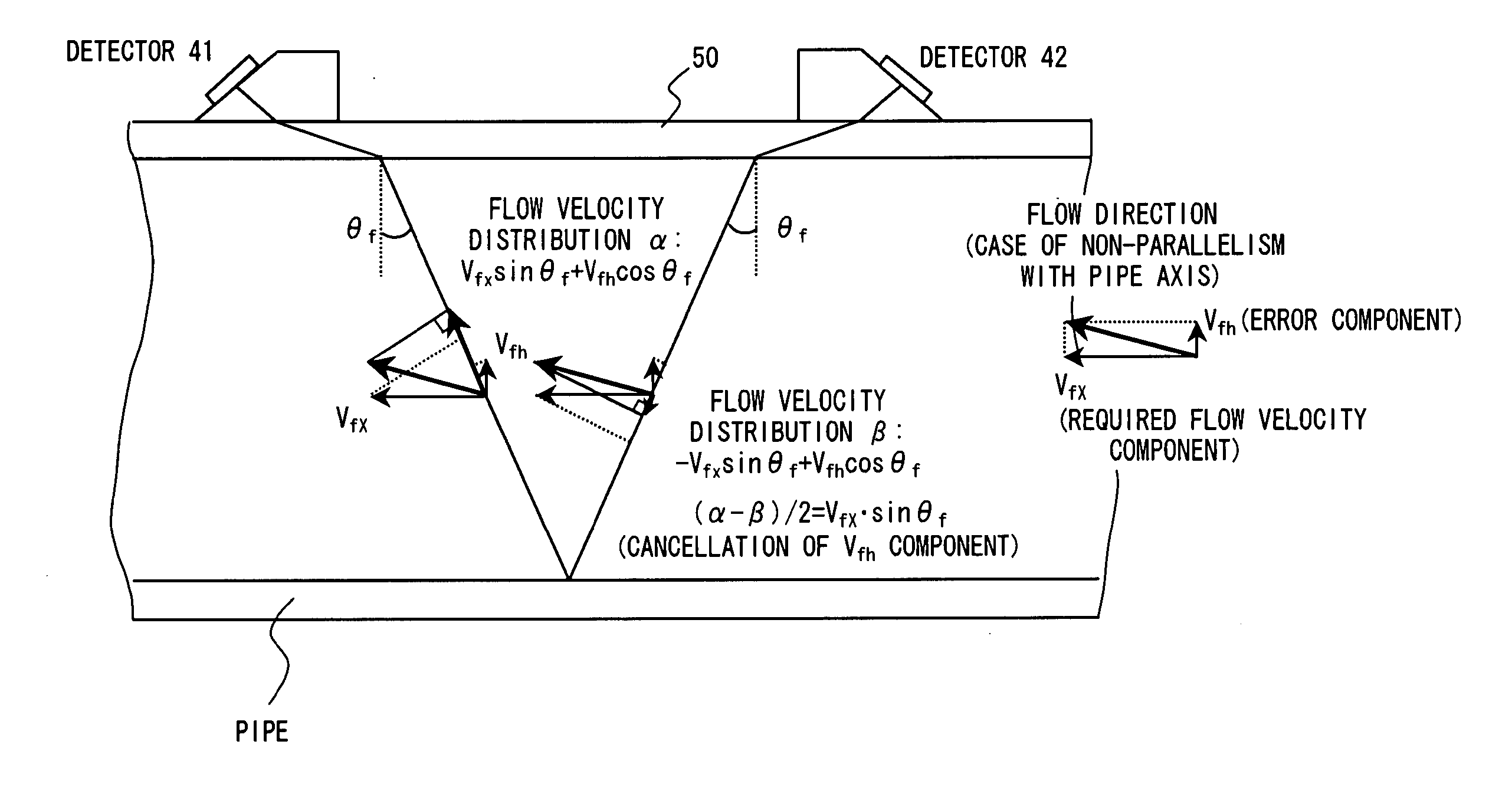
[0097] The embodiment shown by FIG. 6 is configured to place a detector 41 in the downstream of the axial direction on the same side of the pipe 50 and place a detector 42 in the upstream so that the propagation paths of ultrasonic waves emitted from the detectors 41 and 42 form a V shape as a result of being reflected by the wall on the other side of the center axis of the pipe 50 at the time of measurement by the transit time method unit 10. Such a placement method for detectors is summarily called a “V method.”

[0098] And in the embodiment shown by FIG. 6, the transit time method unit 10 causes the detector 41 to send out an ultrasonic wave and measure a flow velocity profile of the fluid 51 in the pipe 50 by detecting an acoustic signal incident on the othe...


PUM


Abstract

A flowmeter includes: a transit time method unit having a sensor and a reception signal amplification control unit and a flow rate calculation unit which are connected to the sensor via a sensor selector switch; a pulse Doppler method having a reception signal amplification control unit and an integration calculation unit which are connected to the sensor; a transmission / reception timing control unit common to them; a measurement method selection control unit for controlling switching between the transit time method unit and the pulse Doppler method unit, and parallel operation; and a measurement value output selector switch for selecting the output of the transit time method unit and the pulse Doppler method unit. That is, the single flowmeter can perform flow rate measurement by the transit time method having no restriction on the measurement range as well as by the pulse Doppler method having an upper limit of the measurement range but enabling a highly accurate measurement.

Description

TECHNICAL FIELD [0001] The present invention relates to an ultrasonic flowmeter for measuring a flow rate of a fluid by emitting an ultrasonic wave into the fluid as the subject of measurement, and in particular to an ultrasonic flowmeter and ultrasonic flow rate measurement method effectively applicable to a flow rate measurement of diverse kinds of fluid, et cetera. BACKGROUND ART [0002] A clamp-on type ultrasonic flowmeter for installing a detector on the outer wall of a pipe, emitting an ultrasonic wave into a fluid flowing in the pipe from the outside of the pipe, and measuring a flow rate on the inside of the pipe by measuring a change of the ultrasonic wave propagating within the fluid has many advantages such as an existing pipe not requiring specific installation work, and a minimal influence by the temperature or pressure of the fluid or its corrosiveness. [0003] There are known techniques as a flow rate measurement method for such a flowmeter, such as the pulse Doppler me...

Claims


Application Information

Patent Timeline
IPC IPC(8): G01F1/66G01F7/00
CPCG01F1/662G01F7/00G01F1/667G01F1/663
Inventor KISHIRO, MASAMIHAGIWARA, KOUJIYAMAMOTO, TOSHIHIROYAO, HIRONOBUOHMURO, YOSHINORIHIRAYAMA, NORIMOTO
Owner FUJI ELECTRIC CO LTD
Why Eureka
Try Eureka